Sometimes there is a desire to assemble some kind of electronic device, not very complicated, but at the same time very interesting. And if it also turns out to be useful, that’s absolutely beautiful. For those people who don’t know what to do with themselves on a long weekend, or simply for those who are interested in doing something with their own hands, I suggest you assemble a simple shock sensor.

Scheme
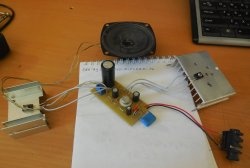
The diagram of this device is presented below:

The sensitive element of the circuit is a piezodynamic, an element that generates electric current at the slightest deformation. It is he who will detect the impact and send a signal to the input of the operational amplifier. You can get such a piezodynamic speaker from some squeaking toy, an electronic watch with an alarm clock, a calculator, or just buy it in a store. It looks like this:

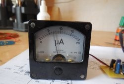
It is enough to touch or hit it a little, and the needle of the microammeter will jump up. A trimming resistor should be placed in series with the microammeter to adjust its sensitivity. The circuit uses a single operational amplifier LM358; you can also use its analogues, for example, TL071.The minimum supply voltage depends on the choice of operational amplifier, if you use LM358, then the minimum supply voltage will be 3 volts, if you take TL072, then the circuit will operate from at least 7 volts. The supply voltage should not be increased above 16 volts.
The low-resistance resistor R4 in the circuit sets the sensitivity. The lower its resistance, the more sensitive the circuit becomes even to small impacts. You should not lower its resistance below 0.33 ohms; the sensitivity of the circuit is already enough. Instead of the arrow head, you can put Light-emitting diode, then it will blink in time with the beats.
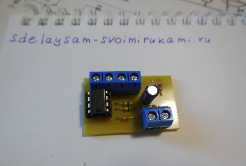
A few words about connecting the piezodynamics. It consists of two plates, one of which is larger in diameter than the first. The central plate, smaller in diameter, should be connected to pin 3 of the microcircuit, and the larger plate, respectively, to the adjacent contact on the board. The printed circuit board contains two contacts for connecting power, two contacts for connecting a piezodynamic speaker and two for output, i.e. connection of the arrow head or LED. It is most convenient to install screw terminal blocks to connect and disconnect wires from the board without the help of a soldering iron.
Manufacturing
Download PCB:
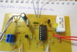
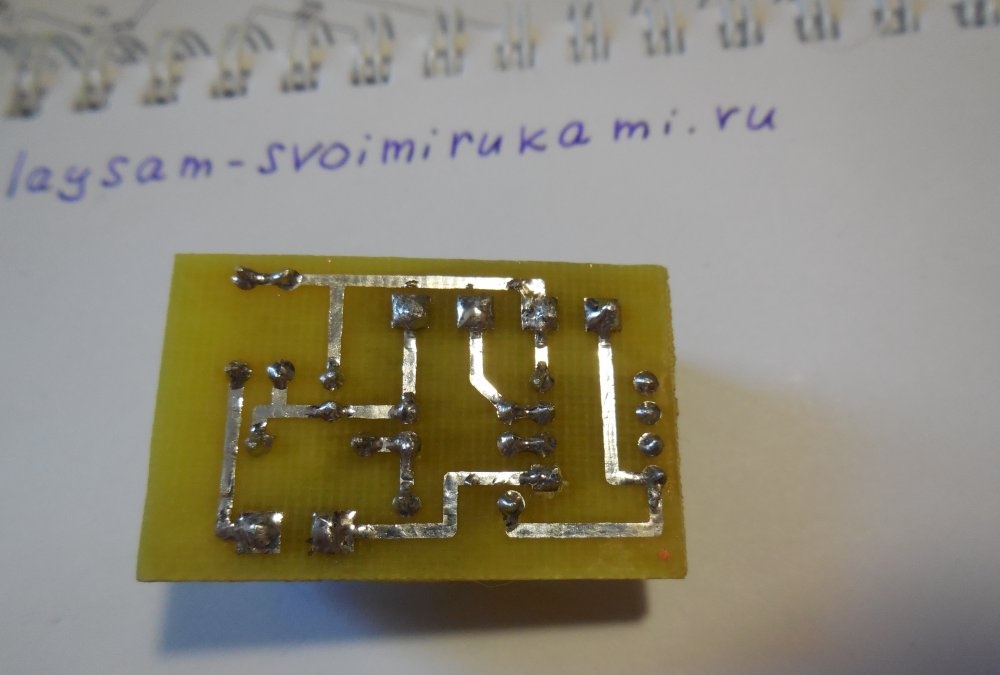
The printed circuit board is made using the LUT method and it looks like this:


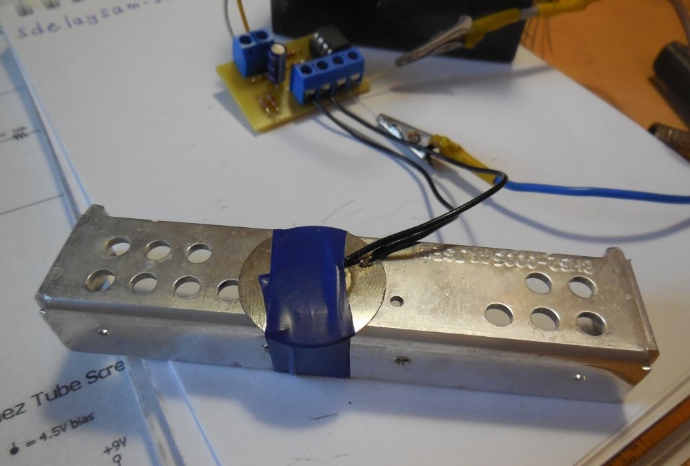
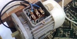
The piezodynamic speaker should be mounted on a massive solid object that will transmit vibrations. You can attach it to the front door, and as soon as someone knocks on it, the circuit will register the knock and notify the owner.
Watch the video of work
The operating principle is clearly shown in the video: