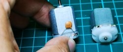
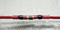
Very often in electronic circuits, in addition to a series (limiting) resistor in the circuit LED, a parallel (shunt) resistor is also added.
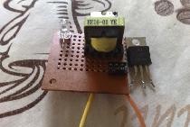
A similar shunt resistor can also be seen in switching power supplies, which is connected in parallel with the optocoupler LED.
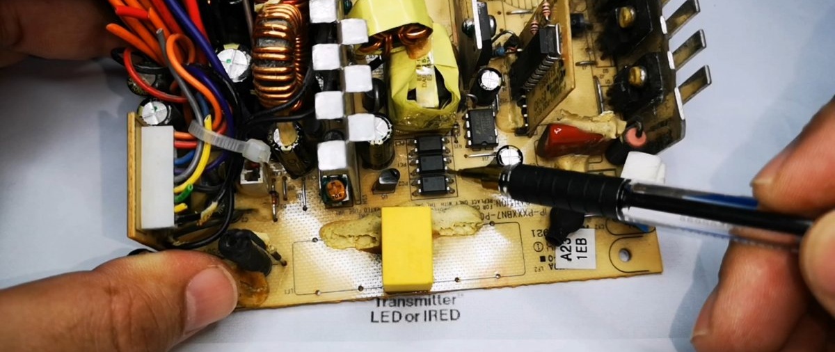
If you turn the board over, you can clearly see it.

What is this shunt resistor for?
Any Light-emitting diode in the circuit it is switched by electronic components: transistors or microcircuits. It is well known that there is no ideal dielectric and even a closed transistor is not a big one, but a conductor. That is, each element in the circuit has a leakage current.
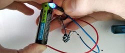
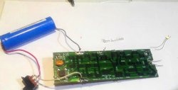
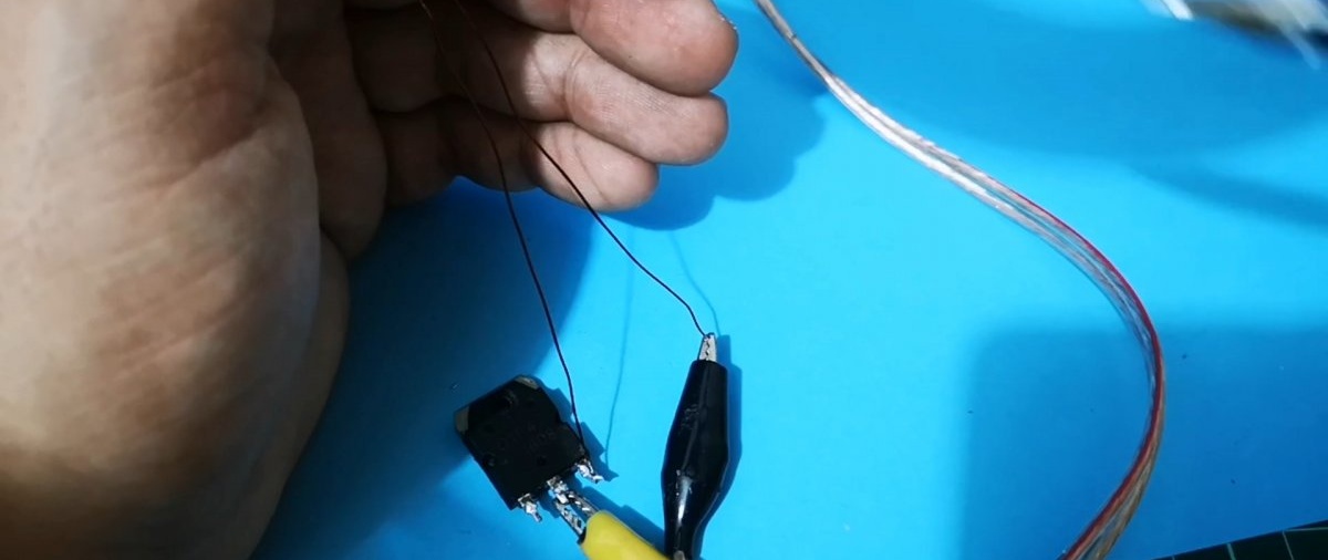
Let's check it using the example of a field-effect transistor.

Let's put multimeter to measure high resistance and “ring” the transition of the closed transistor.

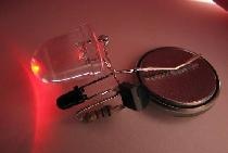
As can be seen from the numbers, there is a leak, although it is insignificant. But if she goes through Light-emitting diode, then this microcurrent is quite enough to ignite it.
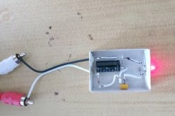
And if you connect a resistor in parallel, then the glow LED stop because the leakage current is not enough.
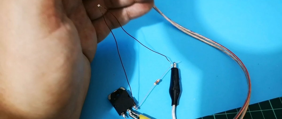
Result:
The result is this: Shunt resistor solves false glow problems LED from leakage currents. This is the first, but not the only one.
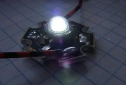
Second: an LED sometimes requires a tiny current to glow, so it can glow not only from leakage of radio elements, but also from “current pickup” that occurs in radio electronics circuits. There are especially many such “interferences” in switching power supplies. This is why optocouplers are actually shunted with resistors.