Do it yourself
Life hacks, master classes, useful tips, recipes.
home » Electronics » Simple circuits » Wireless LED
Wireless LED

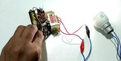
I'll show you a way to make Light-emitting diode glow without connecting wires to it. To do this, you will need to assemble a simple device using a single transistor. And you can prank your friends by showing them your magical abilities.
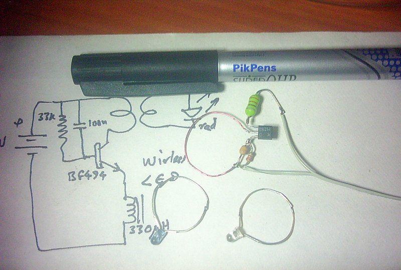
Scheme


Wireless LED

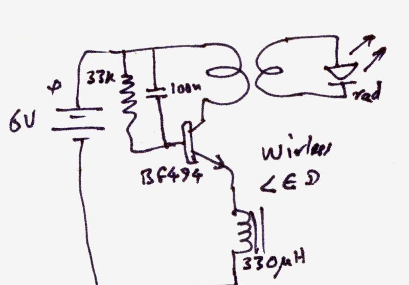
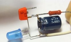
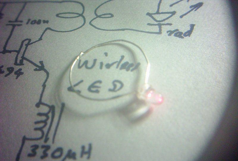
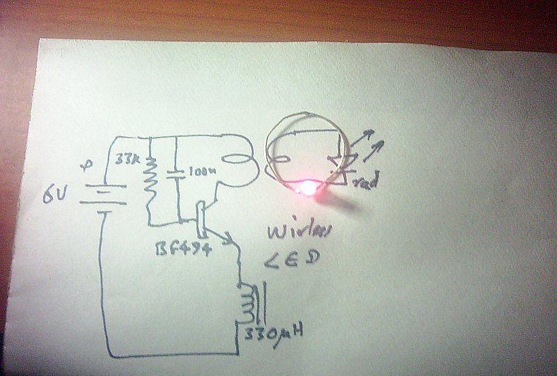
Schematic diagram of one transistor. This is an almost classic high-frequency generator with an inductor and feedback.
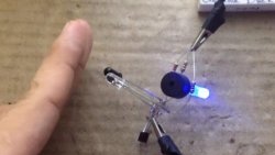
The inductor is a wire made in the form of a round loop. Light-emitting diode also has a receiving loop. When these loops are combined at a certain distance, energy is transferred to the LED and it begins to glow.
The entire circuit is powered by AA batteries.
You may be wondering - where is the feedback in this generator? The generator operates at a very high radio frequency. And a capacitor for feedback is not required, since the transistor body itself has a small capacitance. Plus, the inductances are located very close to each other.

Details for the circuit
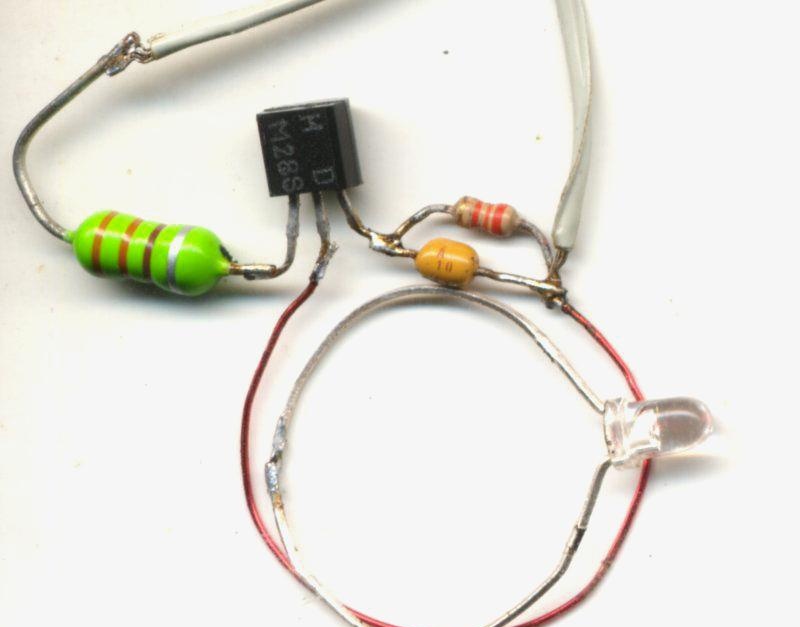

Wireless LED

Parts List:
1. Batteries - 6 pcs.
2. One red Light-emitting diode.
3. Transistor, type BF494 or similar.
4. Capacitor 0.1 uF.
5. Resistor 33 kOhm.
6. Inductance 330 μH.
Wires, solder, etc. as needed.
For the inductor loop - any piece of single-core wire, not very thin.

The LED itself


Wireless LED

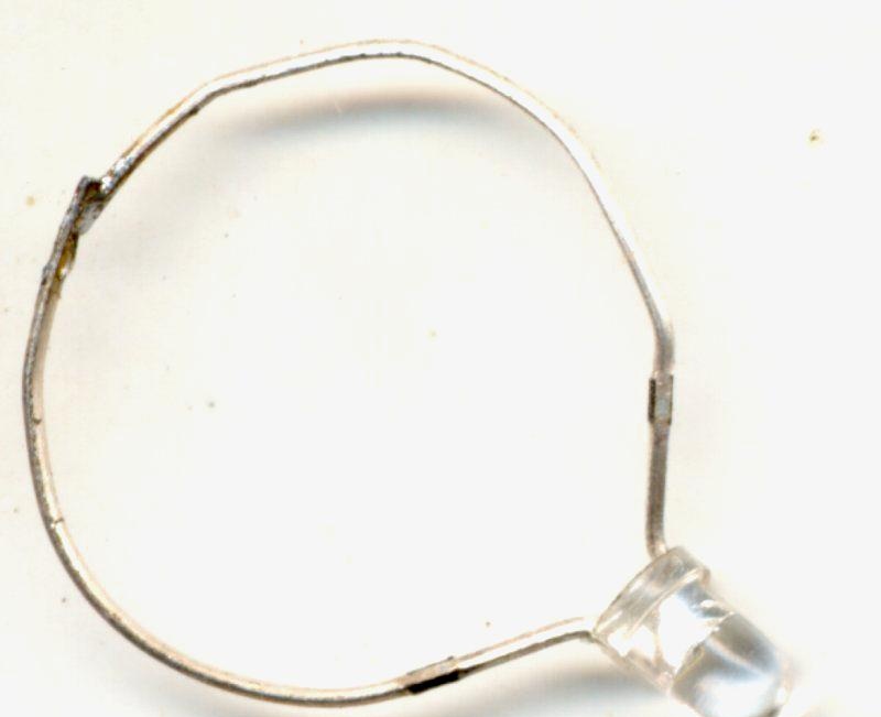
Light-emitting diode will require improvement. Its output needs to be bent into a ring and soldered. All. The receiving indicator of high-frequency radiation is ready.

Making a generator


Wireless LED

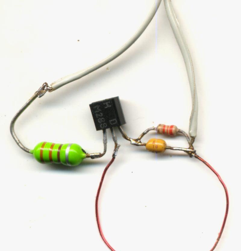
It is very advisable to solder everything as in my drawing.
I also assembled two rings with an LED. One is red, the other is blue. Yes, just in case.
Wireless LED

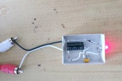
Connect the generator to a power source. And we bring it Light-emitting diode, if it lights up, everything is working.
Wireless LED

Next, we check the distance at which the LED operates. It will be about a few centimeters.
Now all that remains is to secure the circuit and batteries under the table and surprise your friends with a fun and unusual gift. All the best!

Watch the video


come back
Comment
  • bowtiesmilelaughingblushsmileyrelaxed relaxedsmirk
    heart_eyeskissing_heartkissing_closed_eyesflushedrelievedsatisfiedgrin
    winkstuck_out_tongue_winking_eyestuck_out_tongue_closed_eyesgrinningkissingstuck_out_tonguesleeping
    worriedfrowninganguishedopen_mouthgrimacingconfusedhushed
    expressionlessunamusedsweat_smilesweatdisappointed_relievedwearypassive
    disappointedconfoundedfearfulcold_sweatperseverecrysob
    joyastonishedscreamtired_faceangryragetriumph
    sleepyyummasksunglassesdizzy_faceimpsmiling_imp
    neutral_faceno_mouthinnocent
5+two=
Comments (6)
  1. Guest Mikhail
    #1 Guest Mikhail Guests March 1, 2018 12:40
    6
    This is an interesting article. Might really be of interest. And not some kind of Chinese modules.
  2. 123123
    #2 123123 Guests 7 April 2018 16:56
    7
    It doesn’t work, I don’t know why... I’m just learning (I’ve been sitting on it for two days now... I even soldered it again, it still doesn’t want to. Everything is exactly the same... how can I check what the reason is?
    1. kpavp
      #3 kpavp Guests 4 December 2018 21:12
      3
      doesn't work because + and - LED closed
    2. kotanz
      #4 kotanz Guests February 13, 2019 01:50
      7
      Check the polarity of the source connection, the serviceability and pinout of the transistor, the absence of a short circuit in the inductance, and the values ​​of the resistor and capacitor. The transistor may not match the specified frequency (increase capacitance and inductance). To check the operation of the device, you can connect a diode instead of the output loop circuit directly in the opposite polarity to the transistor so that the light does not come from the power source, but only from the generator. If it lights up, then the generator is working, but there is a weak inductive coupling with the diode. You can wind more turns on each loop.
  3. Engineer Vasily
    #5 Engineer Vasily Guests 28 February 2020 20:25
    5
    You should learn to use a ruler, the diagram is hard to read. Well, not bad
  4. Vladislav
    #6 Vladislav Guests 19 April 2023 02:04
    2
    Why is there a 330 µH inductance here?
    Explain the stages of the circuit, please
    1. current flows through the capacitor to the base of the transistor, opening the switch; current flows through the load to the collector, to the emitter and is shorted to negative through the inductance
    2. The capacitor is charged and prevents the passage of current, and the current passing to the base through the resistor is too small to open the key, so the resistor-capacitor circuit is closed, and the capacitor is discharged through the resistor.
    When the capacitor discharges, the cycle repeats.
    Did I describe it correctly? What then is inductance for?

How to Clean a Very Dirty Frying Pan Without Extra Effort

Crochet violets | Do it yourself

How to quickly weld a hose reel from old car parts

Hairpin in kanzashi style | Do it yourself

«Do it yourself - with your own hands» - a site of interesting homemade products made from scrap materials and items at home. Step-by-step master classes with photos and descriptions, technologies, life hacks - everything a real master or just a craftsman needs for needlework. Crafts of any complexity, a large selection of directions and ideas for creativity.

We recommend reading

Washing machine error codes