Do it yourself
Life hacks, master classes, useful tips, recipes.
home » Computer homemade products » 3G 4G antenna with a range of more than 30 km
3G 4G antenna with a range of more than 30 km

Living far from mobile operator towers, there are problems with coverage. The available signal does not even allow making calls, let alone receiving 3G and 4G Internet. Such problems are easily solved if you assemble a powerful antenna. This can be done from cheap materials. The antenna is capable of picking up a signal even 30 km from the tower.

Antenna materials


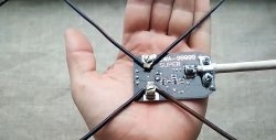
For assembly you will need:
  • all-threaded pin M6 or M8, 140 mm long;
  • nuts for the stud – 12 pcs.;
  • thin sheet metal of any metal;
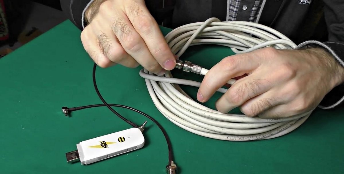
  • coaxial cable up to 12 m long – 2 pcs.;
  • Pigtail connector with adapter – 2 pcs.;
  • F connector for TV cable – 4 pcs.

Necessary theory


Antenna parameters differ for 3G or 4G Internet. The frequency range at which the desired operator operates is important. To assemble the correct antenna you need to know it. To do this, go to your phone's network settings and search for network operators. In the given list with many 2G positions, you need to look only for 3G and 4G. Knowing which operator provides the required coverage in a given area, you can buy a suitable SIM card.
3G 4G antenna with a range of more than 30 km

3G 4G antenna with a range of more than 30 km

3G 4G antenna with a range of more than 30 km

3G 4G antenna with a range of more than 30 km

3G 4G antenna with a range of more than 30 km

3G 4G antenna with a range of more than 30 km

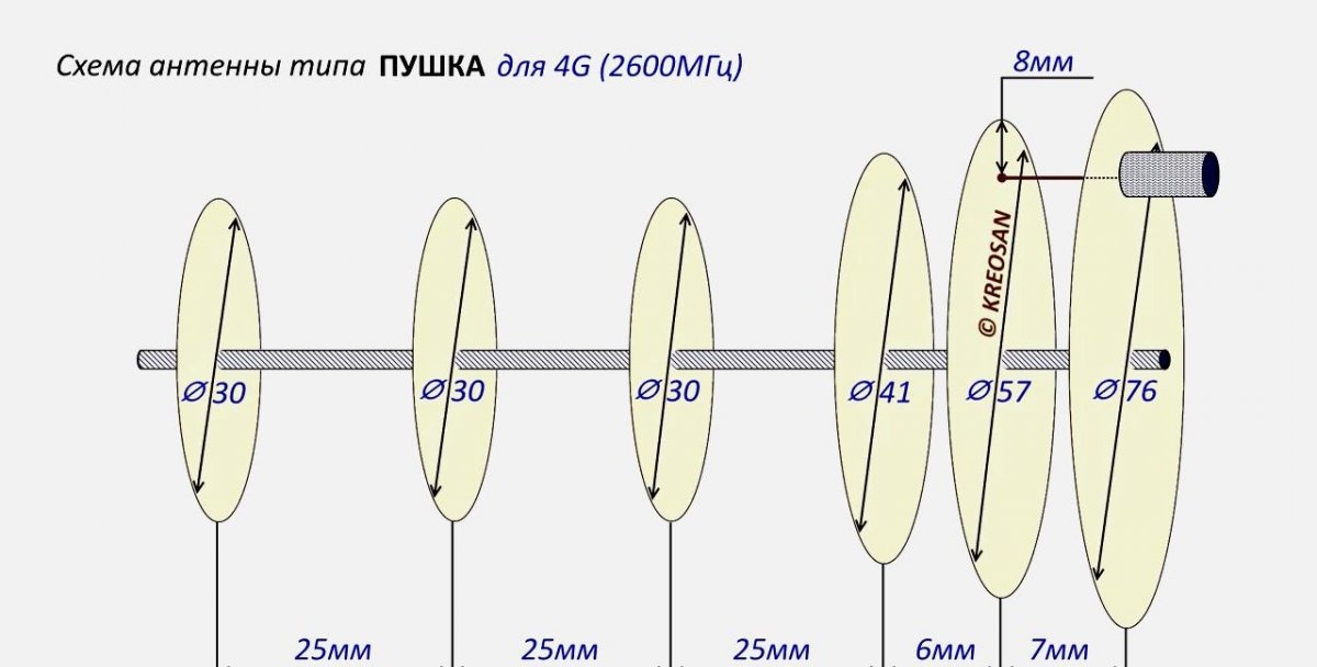
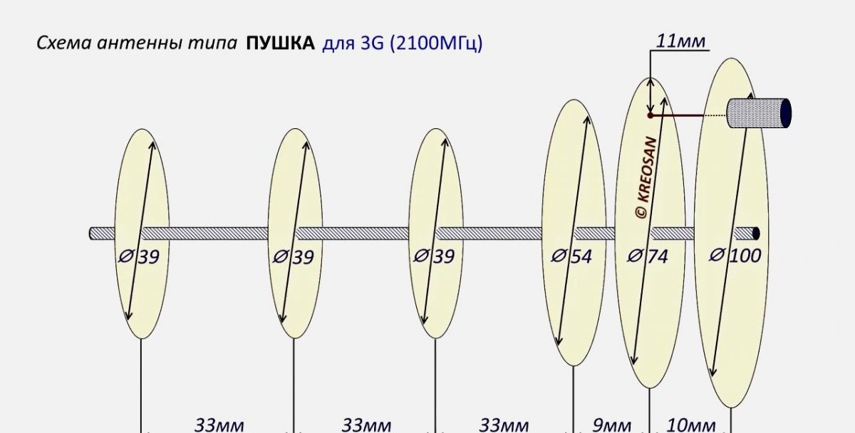
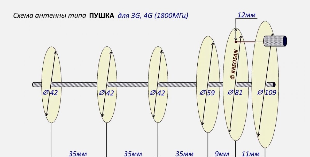
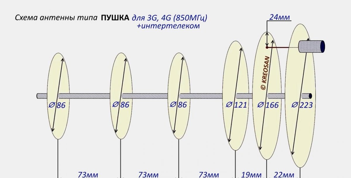
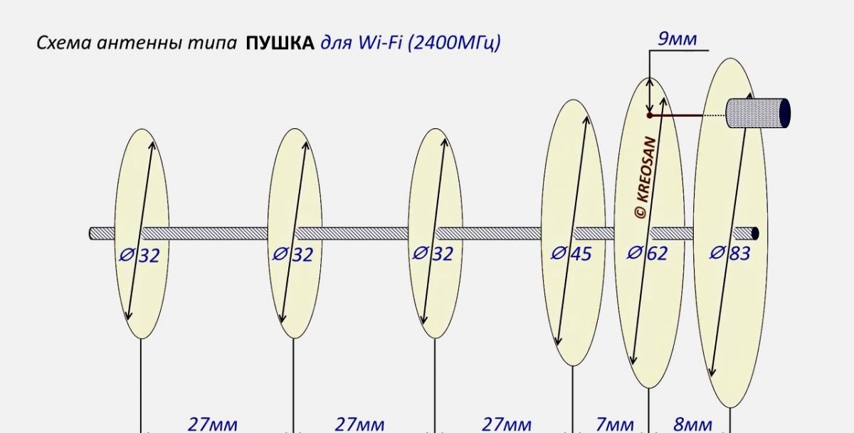
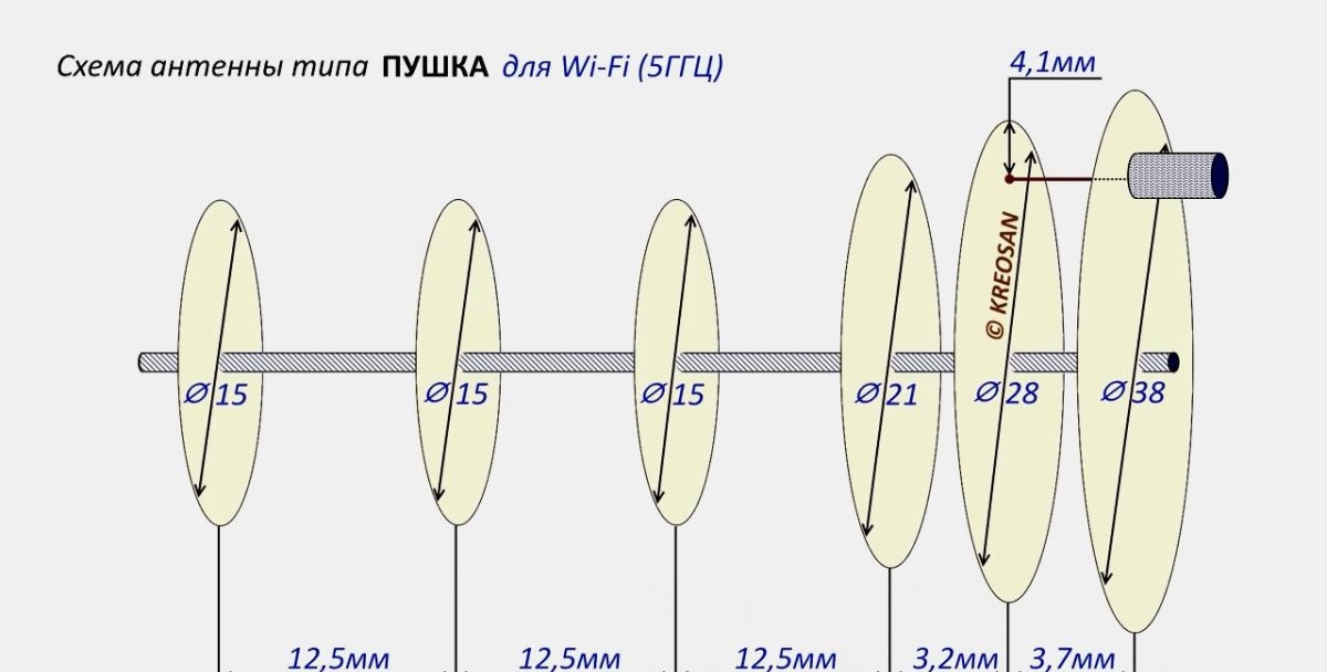
When assembling the antenna, it is important to observe all dimensions down to the millimeter.They are different for each type of network. Typically, the 4G network operates with a frequency of 2600 MHz, in 3G - 2100 MHz. Sometimes 4G and 3G have a frequency of 1800 or 850 MHz. If, when searching for a network, you were unable to find an operator for 3G and there is no information about its frequency, then it is better to make an antenna with parameters of 2100 MHz, as there is a higher chance of catching the signal.

Antenna assembly process


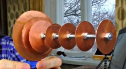
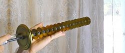
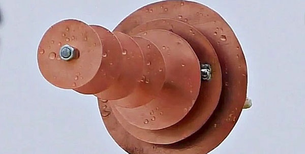
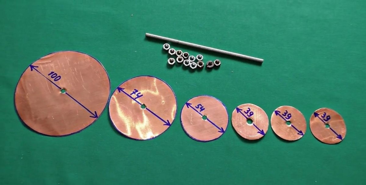
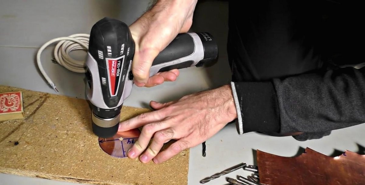
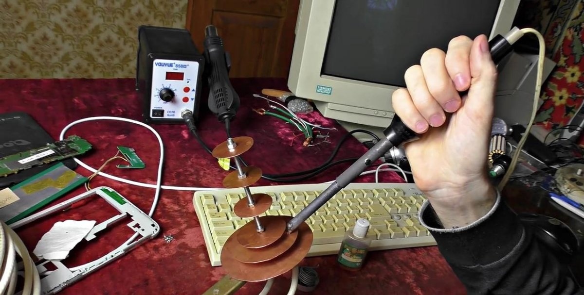
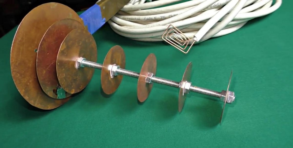
I will be assembling a 3G 2100 MHz antenna. The manufacturing process for devices with different parameters is similar, but differs in the diameter of the segments and the distance between them. First you need to cut 6 disks out of tin. I use thin sheet copper because it is easy to cut with office scissors. The diameters of the antenna segments according to the diagram should be 100, 74, 54, 39, 39, and 39 mm.
3G 4G antenna with a range of more than 30 km

3G 4G antenna with a range of more than 30 km

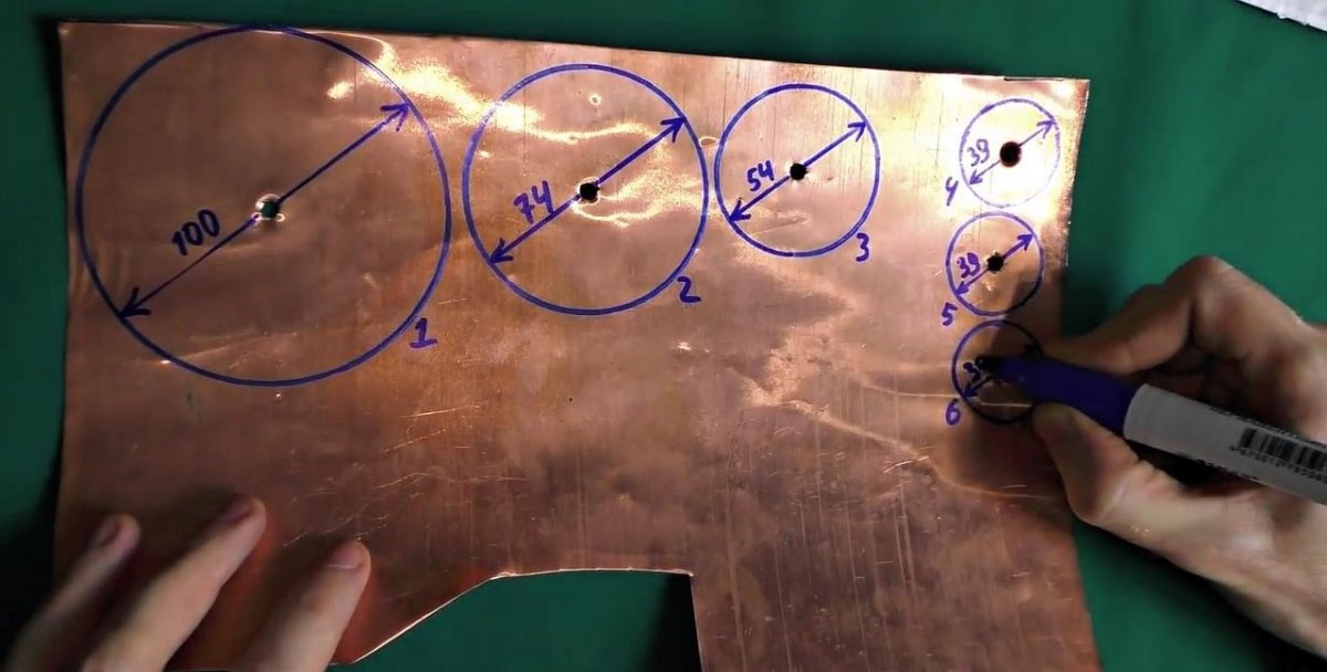
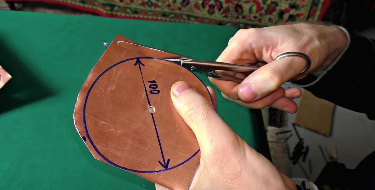
Since it is important to maintain dimensions down to the millimeter, it is better to first drill a hole to match the diameter of the existing stud, and then use a compass to construct a plane for cutting out the disk.
3G 4G antenna with a range of more than 30 km

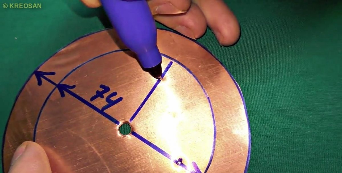
On a disk with a diameter of 74 mm, you need to prepare a hole for soldering the wire strand. It is drilled at a distance of 11 mm from the edge. When working with the 3G range, this antenna requires the connection of 2 coaxial TV wires. The length of each of them should not exceed 12 m. The second hole must also be drilled at a distance of 11 mm from the edge, but at an angle of 90 degrees relative to the first.
3G 4G antenna with a range of more than 30 km

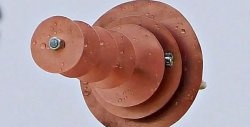
Now, having attached a 74 mm disk to a large 100 mm segment, you need to make markings for large holes for entering the coaxial television cable along with the braid.
3G 4G antenna with a range of more than 30 km

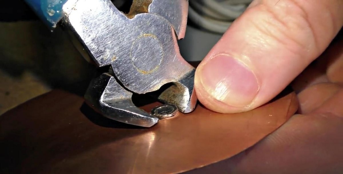
From a pair of ordinary television F connectors you need to break off the protruding part, as I did, and press them into the existing holes on the 100 mm disk. For reliability, it is better to crimp the connectors a little.
3G 4G antenna with a range of more than 30 km

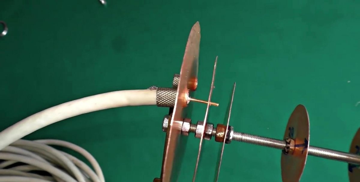
Now you need to fix the disks to the pin in the specified order and in compliance with the distance suggested by the diagram. The distance between the 100 and 74 mm segments is 10 mm, in the next transition between the disks the distance will be 9, 33, 33 and 33 mm, respectively. Each element is secured with two nuts, one on each side.
3G 4G antenna with a range of more than 30 km

During assembly, you need to double-check the distance between the disks, since deviation will lead to a decrease in the quality of signal reception.
3G 4G antenna with a range of more than 30 km

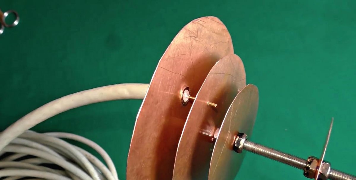
Next you need to connect the coaxial cables to the large drive. This must be done so that the central copper core of each wire fits into a thin hole on the adjacent segment with a diameter of 74 mm. After installation, the wire must be soldered, without bending it in any way.
3G 4G antenna with a range of more than 30 km

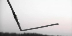
A wooden, plastic or metal strip that acts as a holder must be attached to the protruding tail of the pin on the back of the antenna. For reliability, coaxial cables can be tied to it so as not to create a load on the thin tin disk to which they are soldered.
3G 4G antenna with a range of more than 30 km

3G 4G antenna with a range of more than 30 km

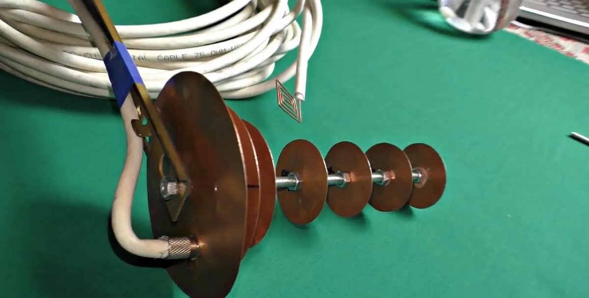
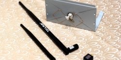
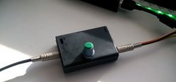
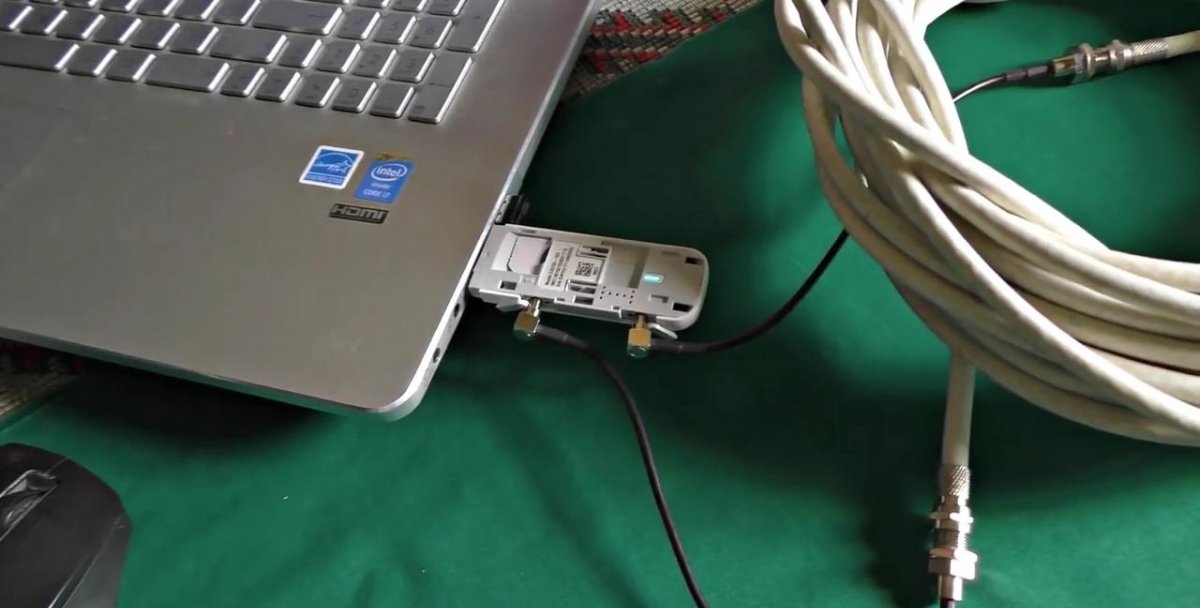
Now you need to attach Pigtail connectors with adapters to the free ends of the coaxial cable. They are the ones that connect to the 3G 4G modem. The antenna is ready, all that remains is to install it.
3G 4G antenna with a range of more than 30 km

3G 4G antenna with a range of more than 30 km

If there is no nest.
3G 4G antenna with a range of more than 30 km

Settings


3G 4G antenna with a range of more than 30 km

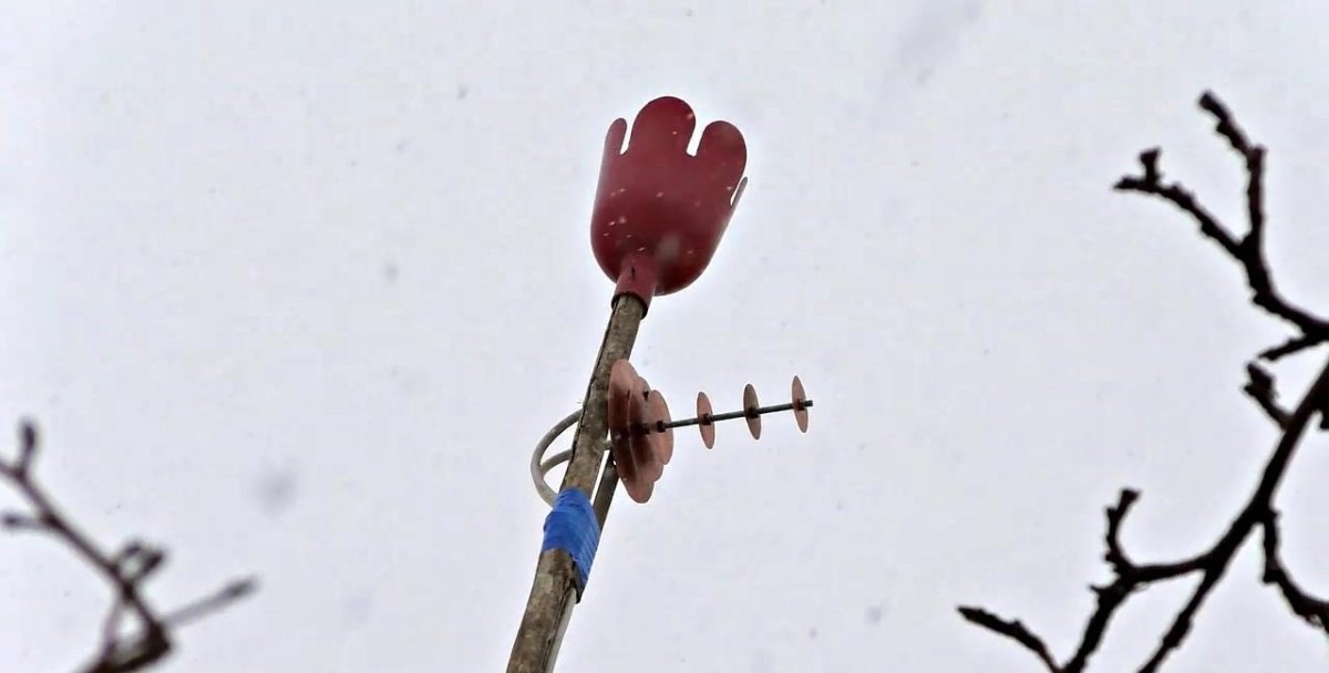
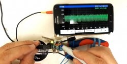
To achieve maximum reception quality, you need to move the antenna outside the room. It needs to be placed slightly higher than the roofs of nearby buildings in order to minimize possible interference and prevent noise. You need to point the antenna directly at the nearest tower that broadcasts the Internet signal. To find out where it is located, you can use the Netmonitor application. Such a simple antenna is capable of picking up signals from towers located at a distance of even more than 30 km.

Watch the video


For detailed testing and manufacturing of antennas, see the video
come back
Comment
  • bowtiesmilelaughingblushsmileyrelaxed relaxedsmirk
    heart_eyeskissing_heartkissing_closed_eyesflushedrelievedsatisfiedgrin
    winkstuck_out_tongue_winking_eyestuck_out_tongue_closed_eyesgrinningkissingstuck_out_tonguesleeping
    worriedfrowninganguishedopen_mouthgrimacingconfusedhushed
    expressionlessunamusedsweat_smilesweatdisappointed_relievedwearypassive
    disappointedconfoundedfearfulcold_sweatperseverecrysob
    joyastonishedscreamtired_faceangryragetriumph
    sleepyyummasksunglassesdizzy_faceimpsmiling_imp
    neutral_faceno_mouthinnocent
5+two=
Comments (85)
  1. Guest Sergey
    #1 Guest Sergey Guests December 18, 2018 10:20
    9
    It’s very similar to OP, but no one is stopping you from trying it. I’ll try it.
  2. Guest Gennady
    #2 Guest Gennady Guests December 18, 2018 10:33
    22
    antennas are not weak, strong, powerful, cool (no offense to the author). If anyone has passed the exam on AFU (antenna-feeder devices) they know that an antenna is characterized by three main parameters - operating frequency, bandwidth and gain, there is also BV and SWR, the nature of the load (capacitive, inductive, active) but this is not so important . Now, if you (and others) provided these characteristics, it would be great. These parameters can be measured using a simple radio beacon, located at 100-200 meters and a measuring receiver. Of course, not everyone has a receiver..... sorry........
    1. Guest aLEKSANDER
      #3 Guest aLEKSANDER Guests 7 January 2019 16:34
      8
      Excuse me, but what is the gain of the passive system? This is called directivity coefficient!
  3. Onandyn.
    #4 Onandyn. Guests December 18, 2018 10:49
    32
    Aftor is a joker, in places with a minimal signal level the modem will work without this gadget, where the signal is extremely weak, two-way is required!!!!!! amplifier. A modem is not a radio receiver; it will not work without sending a signal to the base station. Neighing.
    1. nemo
      #5 nemo Guests December 18, 2018 12:56
      5
      how do you explain the fact that cars used to also have antennas for mobile phones??)))
      1. bugulmek
        #6 bugulmek Guests December 20, 2018 09:13
        2
        no one canceled the amplifiers
        1. reminin
          #7 reminin Guests December 25, 2018 11:33 pm
          20
          The antenna is the amplifier. and this amplifier works without external power supply. Moreover, this is an amplifier with a minimum amount of noise. An electrical signal amplifier amplifies both the signal itself and the noise in the signal.
          1. Guest Alexander
            #8 Guest Alexander Guests 7 January 2019 16:41
            12
            And again, for the smart guys, the antenna is a passive system and it has no gain, it is characterized by other characteristics such as directivity coefficient, the antenna is an open circuit, in other words, a coil with resonance in a certain range, learn physics!!!
            1. Guest Oleg
              #9 Guest Oleg Guests December 12, 2019 11:03
              4
              Beautiful. I respect you. Otherwise, damn it, they’re sick of the passive amplifier, the passive amplifier. Damn, at least someone was able to explain it to the boobies.
            2. OS
              #10 OS Guests 3 November 2020 16:15
              8
              The antenna has no gain, but it has a gain, this is the ratio of the power of the useful signal of an omnidirectional antenna to the power at the output of a directional one; in fact, it can be considered as the ratio of the antenna’s radiation pattern to a “circular” or rather sphere. The analogy is a flashlight emitting light.the wider the beam, the worse the illumination at a distant point; a narrow beam will provide good illumination because all the emitted light will fall on a small spot. the same thing from afar. you can hardly see a candle flame at a hundred meters away, but you will find the same candle at the focus of a reflector a kilometer away. A reflector that concentrates light is a passive object, but it works in much the same way as an antenna. greatly increasing the range of the flashlight.
    2. Konstantin
      #11 Konstantin Guests 18 December 2018 13:35
      9
      Repeaters, in addition to the useful signal, increase the entire bandwidth, including noise, and also introduce distortion, which negatively affects the signal-to-noise ratio. Which, in turn, reduces the connection bandwidth.
      A good antenna with good gain, connected directly to the appropriate connector, is in practice a much more effective option. However, it is also necessary that the cable have a low attenuation level.
    3. Guest Mikhail
      #12 Guest Mikhail Guests 18 December 2018 14:07
      9
      The modem also radiates using this antenna.
    4. aszxx
      #13 aszxx Guests 18 December 2018 15:08
      10
      2nd cable for the transmitter, I think. Otherwise, what is he for? The antenna is directional and is an amplifier.
      1. Guest Alexander
        #14 Guest Alexander Guests 3 July 2019 18:20
        8
        The second wire is for a different polarization. There is vertical, there is horizontal. So, in an antenna made of round disks, a double connection is usually used - one wire to one disk, the second to the other. Then the antenna will operate in two polarizations. Such antennas are called something like MIMO. I advise you to look for instructions on assembling such an antenna. It will be more efficient and easier to manufacture, since it only has two disks.
    5. Guest Vlad
      #15 Guest Vlad Guests 18 December 2018 19:54
      2
      But isn’t the antenna a transmitting and receiving antenna?
    6. Guest Sergey
      #16 Guest Sergey Guests December 18, 2018 11:34 pm
      15
      Learn physics, in this case the transmitter does not spread the power around the area, but with the help of an antenna concentrates it in a certain direction, I can laugh at you too...
      1. kegelm
        #17 kegelm Guests December 20, 2018 09:14
        3
        only with standard connection
      2. Michael
        #18 Michael Guests 30 May 2020 10:53
        4
        Something I can’t understand is how the receiving antenna can affect the gain of the received signal?
        1. Guest Anatoly
          #19 Guest Anatoly Guests May 31, 2020 11:23
          9
          Any antenna has its own gain, radiation pattern... The subject “Radio Engineering and Antennas”, at least within the scope of a technical school, will help you...
    7. Ivan
      #20 Ivan Guests 20 December 2018 19:59
      5
      In fact, this antenna also works in the opposite direction, that is, for transmission
    8. OS
      #21 OS Guests 3 November 2020 16:00
      4
      The radiation pattern, as well as the gain, of the antenna are the same for both reception and transmission. If reception has improved with the help of an antenna, then transmission in the opposite direction will also be better, almost equally. Therefore, a directional antenna allows you to organize not just reception, but a bidirectional communication channel.
  4. Guest Oleg
    #22 Guest Oleg Guests December 18, 2018 12:20
    3
    The nuts and stud are also copper - that would be nice ;)
    1. Guest Sergey
      #23 Guest Sergey Guests April 2, 2019 11:45
      8
      Why copper? Maybe gold! Or you can even use a tester to drive nails and a head into the wall! Where the stud and nuts have zero potential at all, there is at least a piece of wood, even copper, even cast iron, even textolite - the main thing is the external dimensions of the vibrator, reflector, directors and the distance between them, and the stud and nuts do not play any role at all! Unless it’s about the strength of the structure and if it’s metal, it can (and should) be grounded - excellent lightning protection will be provided when installing a high mast!
    2. OS
      #24 OS Guests 3 November 2020 16:19
      1
      The nuts and stud in this design are just a structural element. They can be replaced with a plastic pin, the antenna will work, if not the same, then perhaps even better than with metal ones.
      1. WR
        #25 WR Guests 14 July 2022 20:52
        1
        Can I take CDs? will it work too?
  5. Innocent
    #26 Innocent Guests 18 December 2018 14:39
    8
    Lies! Did
  6. Zhorik
    #27 Zhorik Guests 18 December 2018 19:54
    8
    It's like pounding, that's what our guys from Lugansk do.
  7. Radio engineer
    #28 Radio engineer Guests December 19, 2018 09:12
    8
    Connect TWO cables to ONE antenna - NOBODY has thought of this before! To the author - the Nobel Prize in Physics!
  8. Alexey Ageev
    #29 Alexey Ageev Guests December 19, 2018 10:42
    2
    I made one for Wi-Fi. I connected it to the router and directed it to the router, which stood on the 5th floor near the window from the parking lot 150 meters away. The signal was one stick, it consistently gave out 1Mbit for downloading and some pennies for sending. It was necessary to direct very accurately.
    I also had a Chinese Wi-Fi “plate” with me, they sell black and white ones for 500 rubles, with it the result was the same.
    Maybe I didn’t assemble the antenna accurately enough, but this is the result of the experiment)
  9. Guest Alexander
    #30 Guest Alexander Guests December 19, 2018 12:33
    10
    Even from the photo it is clear that the antenna has a large intrinsic capacity. This indicates its broadband and small coefficient. gain. Add a cable to it and all the “gain” will go to a big “minus”. There is no point in fiddling with this “toy”. And I’m generally silent about weak signals.......
  10. Qteam
    #31 Qteam Guests 19 December 2018 19:43
    7
    So - I didn’t understand - the F-connector is usually connected to the cable braid. For you it connects to the first pancake. From the first pancake to the second there is contact along a metal pin. The second pancake connects to the central core. - as a result, we get one common cable to the end of which some kind of knob was attached. Where the hell will your potential difference live then? Between the antenna itself as a whole and the ground. The higher you raise it, the better the fishing will be - and you don’t care about the distance between the pancakes - you get a braided main waveguide.
    1. Guest Anatoly
      #32 Guest Anatoly Guests 20 December 2018 19:47
      9
      What the hell is the potential difference, the frequencies are GHz.
      1. Borga
        #33 Borga Guests 20 July 2019 13:23
        1
        are they not there? Ig Nobel to the studio!!!
      2. Borga
        #34 Borga Guests 20 July 2019 13:49
        5
        this same potential difference is Always. This means nodes and antinodes, which are certainly present in the radio range (any). Your product a priori does not have polarization, and therefore does not have outstanding signal “amplification” capabilities. Maybe you remember the antennas of the Lunokhod? where accuracy is needed - don’t care about polarization, we’ll pump in a megawatt for control and receive the signal with a 25-meter parabola and fig at it, at polarization... from the ship, why, let the bourgeoisie tremble. Oh, I’m in the wrong place - sorry..

How to make a roof from plastic bottles

How to cook lard in a slow cooker

Useful and interesting | Page 46 | Do it yourself

How to make an attachment for a multimeter

«Do it yourself - with your own hands» - a site of interesting homemade products made from scrap materials and items at home. Step-by-step master classes with photos and descriptions, technologies, life hacks - everything a real master or just a craftsman needs for needlework. Crafts of any complexity, a large selection of directions and ideas for creativity.

We recommend reading

Washing machine error codes