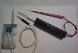
Materials:
- 3.5 mm plug from headphones;
- wires;
- heat shrink;
- Zener diode 2.2V;
- resistor 2.2K;
- resistor 1K;
- test clip;
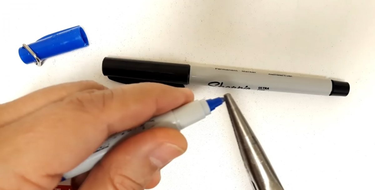
- marker body;
- furniture nail.
Oscilloscope assembly
The figure shows a diagram of a simple oscilloscope - a probe for a smartphone, which needs to be repeated. It is very important to use resistors with the same color coding as in the example, as this will allow you to get maximum sensitivity and accuracy from the device.
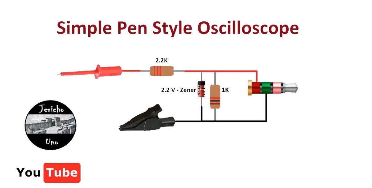
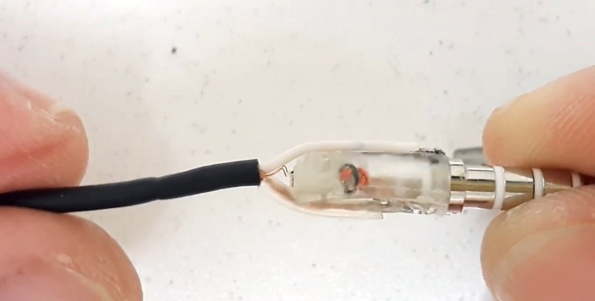
Assembly should begin by preparing the 3.5 mm mini-jack plug from the headphones.The plastic part is cut off from it, after which 2 wires are soldered as shown in the oscilloscope diagram.
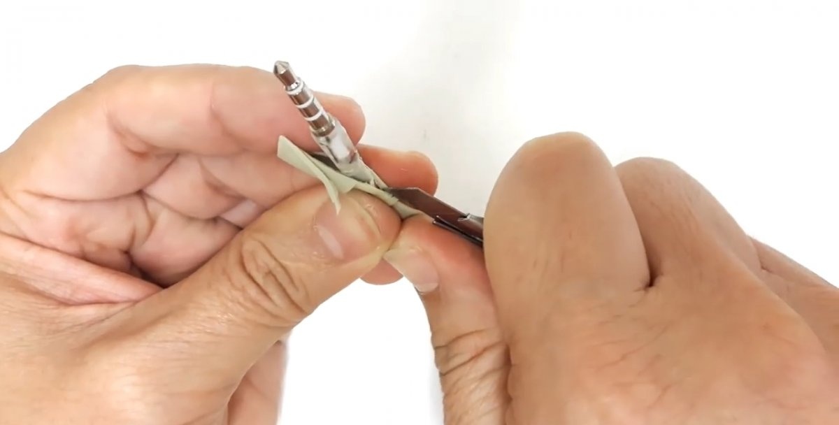
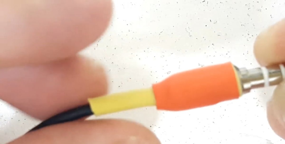
Soldered wires must be additionally secured and insulated. To do this, it will be enough to use 2 layers of heat shrink tube.
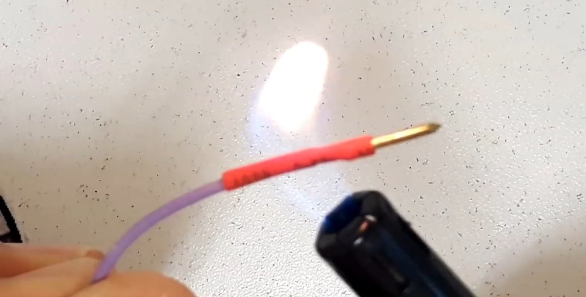
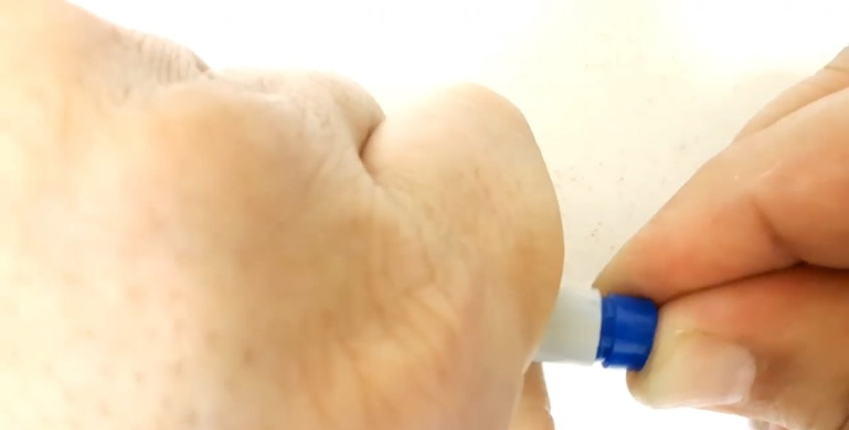
Next, you need to solder a single-core wire to the head of a small furniture nail.
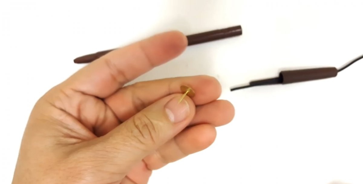
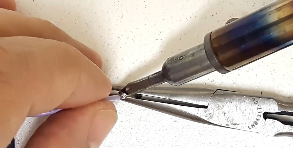
The soldering area on top is insulated with heat shrink. The nail will serve as a positive electrode.
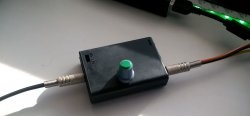
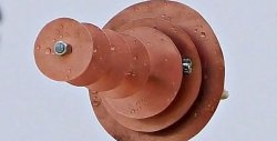
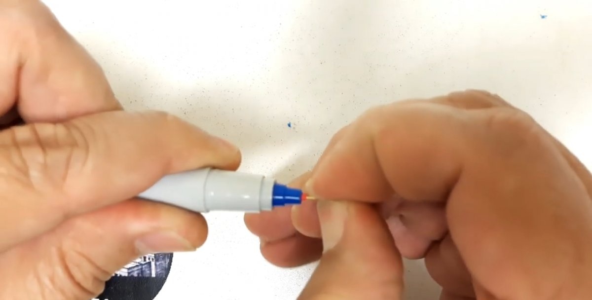
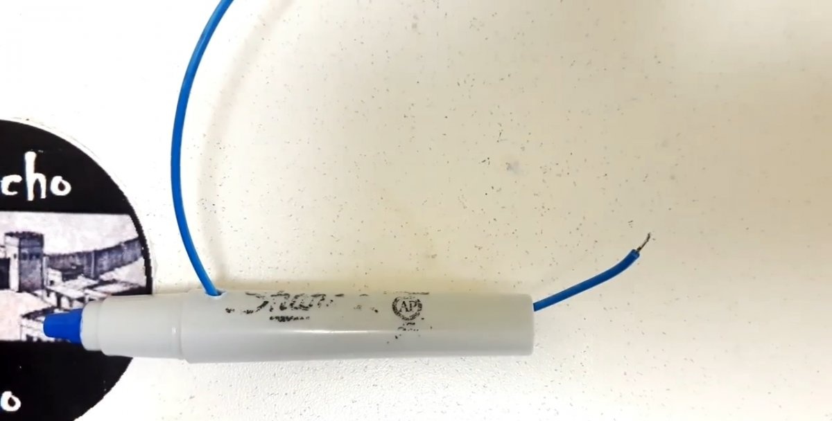
The wire with the nail is inserted into the marker body with the rod removed. As a result, the electrode must replace the writing tip of the felt-tip pen. You also need to run the wire from the 3.5 mm connector into the punched hole in the back cap of the marker.
Next, you need to connect in parallel and solder the zener diode with a 1K resistor. According to the device diagram, a 2.2K resistor is soldered to them.
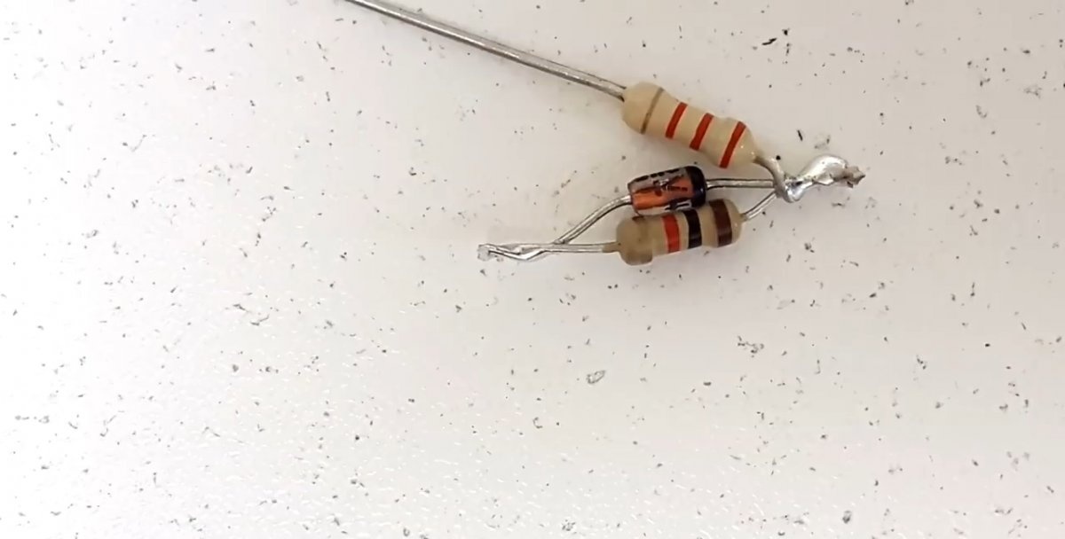
A side hole is made in the marker body closer to the writing part. A separate wire is threaded into it, the second end of which comes out of the back of the felt-tip pen.
A zener diode with a 1K resistor is soldered to the output wire. You also need to connect the power cable from the 3.5 mm jack to them. It is important to maintain the polarity, as in the diagram. The second wire from the mini-jack is soldered to a 2.2K resistor.
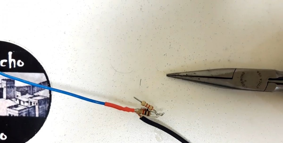
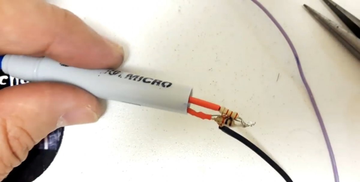
The wire with the nail must be connected to the remaining end of the 2.2 K resistor. All connections are protected with heat shrink. After this, the resistors and the zener diode must be hidden in the marker body, closing it with the back cap.
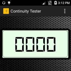
You need to solder a test clip to the wire coming out of the side of the marker, connected to the 1K resistor and the zener diode.
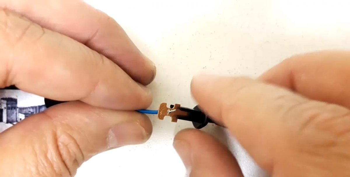
After this, the hardware of the device is completely ready.
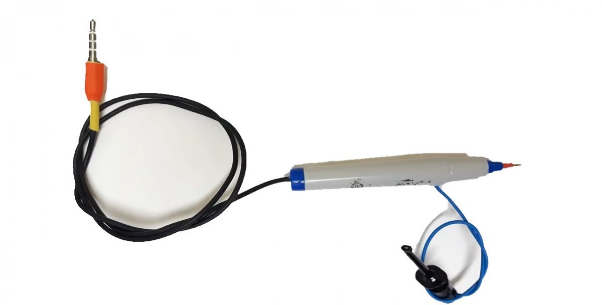
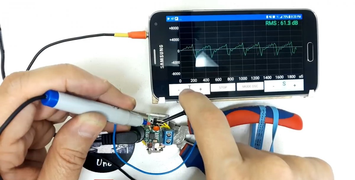
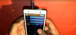
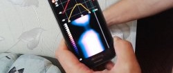
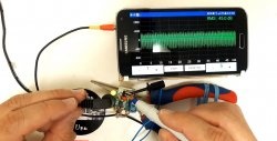
Next, you need to install the Oscilloscope Pro 2 application on your smartphone. The oscilloscope connects to the phone and can be used for its intended purpose under the control of this program.His test clip is used as a ground and the stud electrode on the marker is a plus. The application in conjunction with a homemade device allows you to set response thresholds, view the signal shape on the display and much more.