Many people like to listen to the radio - at home, in the car, at work, while doing what they love, because broadcasting on VHF frequencies (88-108 MHz) is carried out in every major populated area. However, few people know that you can build a high-quality radio receiver on a microcircuit yourself; it does not contain scarce or expensive components. Its basis is a microcircuit TDA7021, which is available in both DIP and surface mount packages. Its complete domestic analogue is the K174XA34 microcircuit. The output of the radio receiver is connected to the input of the amplifier on a known microcircuit TDA2003, which can work with both speakers and headphones.
Scheme
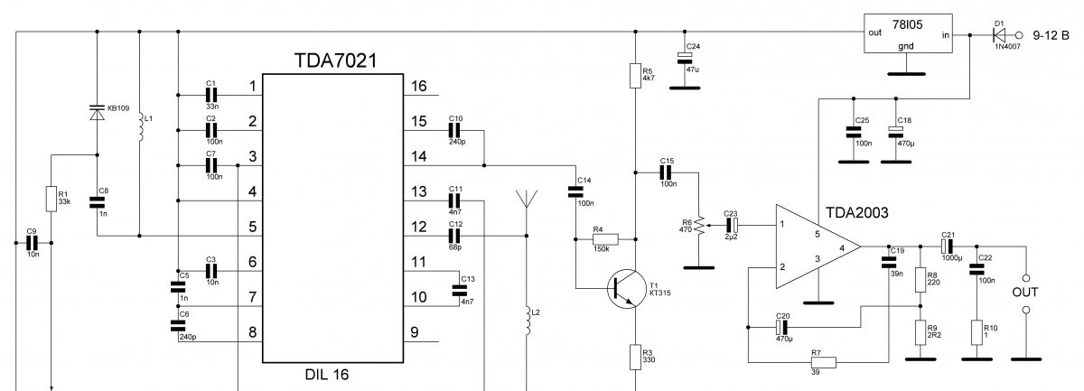
Potentiometer R2 is responsible for tuning to the desired radio station; it changes the voltage on the varicap. You can take any with ratings of 50-100 kOhm. Potentiometer R6 regulates the sound volume; any resistance of 470 Ohm - 1 kOhm is suitable. Transistor T1 is a low-power NPN structure, suitable for KT315, BC547, 2N3904 and other similar ones. It is worth considering that they have different pinouts; the board in the article is designed for KT315. Varicap KV109 with any letter, I used KV109B.
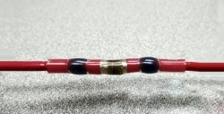
- Coil L1: 8 turns of wire with a diameter of 0.5 mm.
- Coil L2: 13 turns of wire with a diameter of 0.5 mm.
The coils are wound with enameled copper wire, turn to turn, on a mandrel with a diameter of 3 mm. It is most convenient to wind it on a drill of a given diameter, in our case 3 mm. Then the wound coil is removed from the drill and soldered into the board. It is not necessary to strictly observe the diameter of the wire for winding - but you should choose the one closest to 0.5 mm.
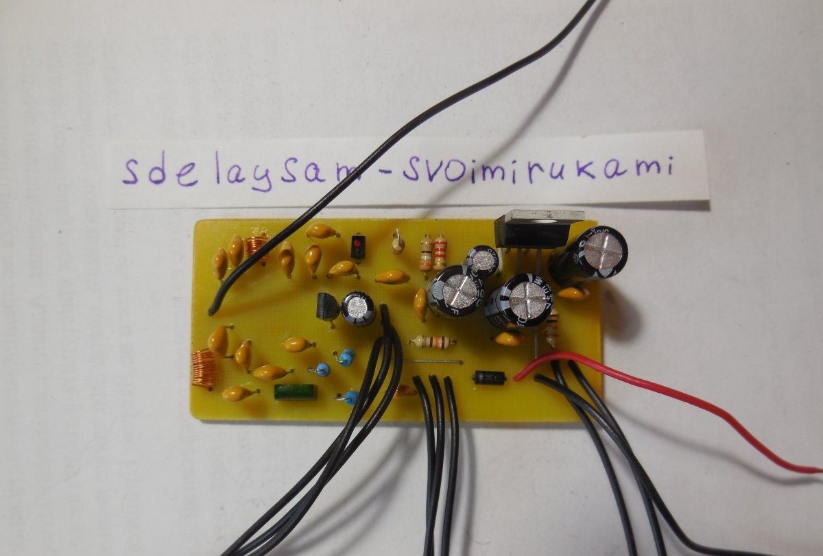
Receiver assembly
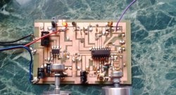
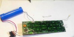
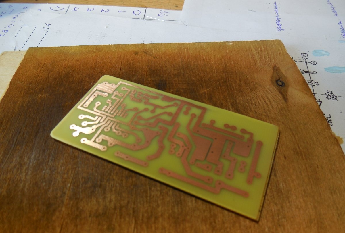
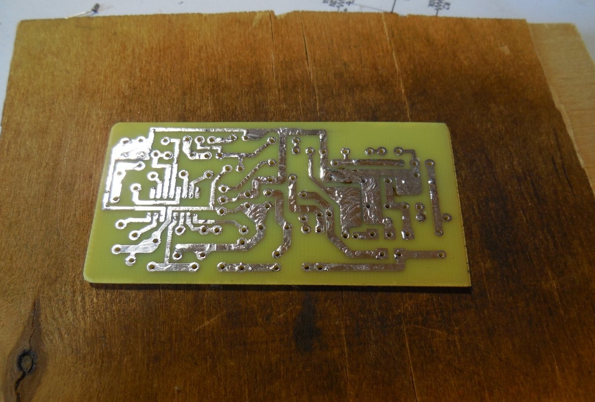
The receiver is assembled on a printed circuit board, the file of which is attached to the article.
The board is made using laser-iron technology.
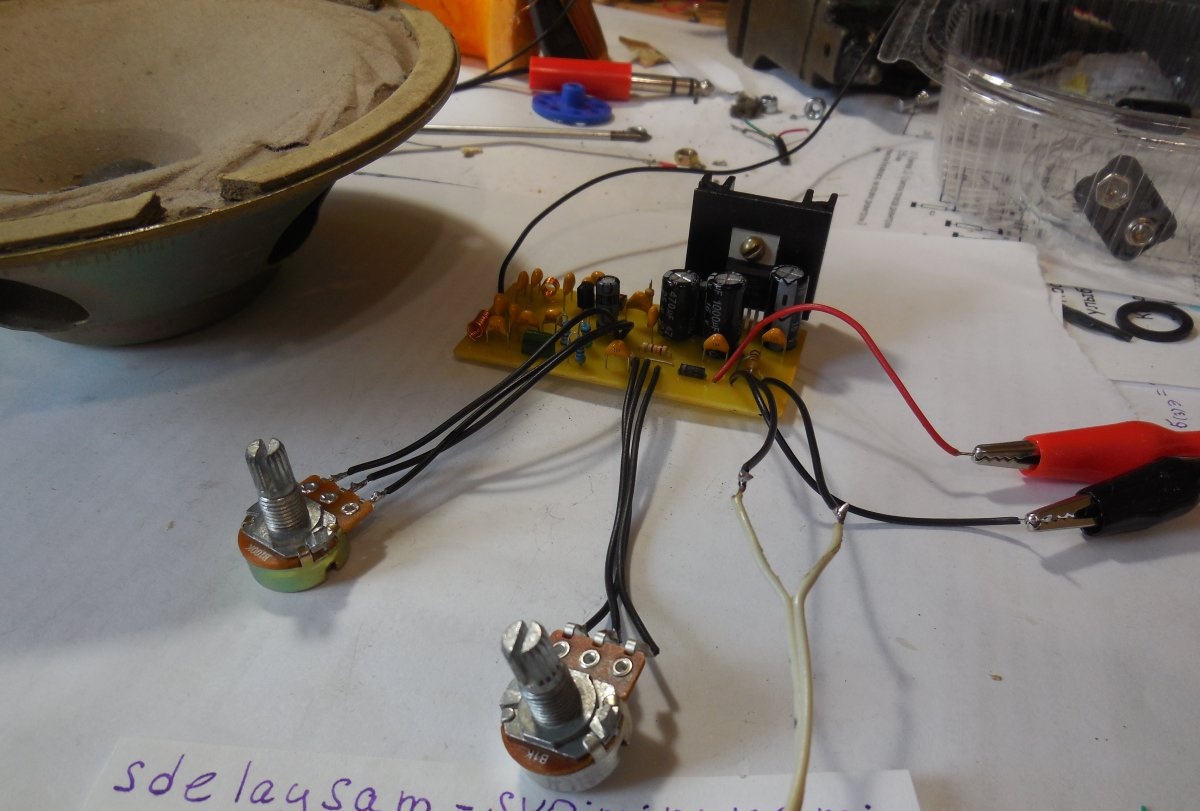
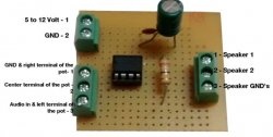
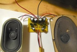
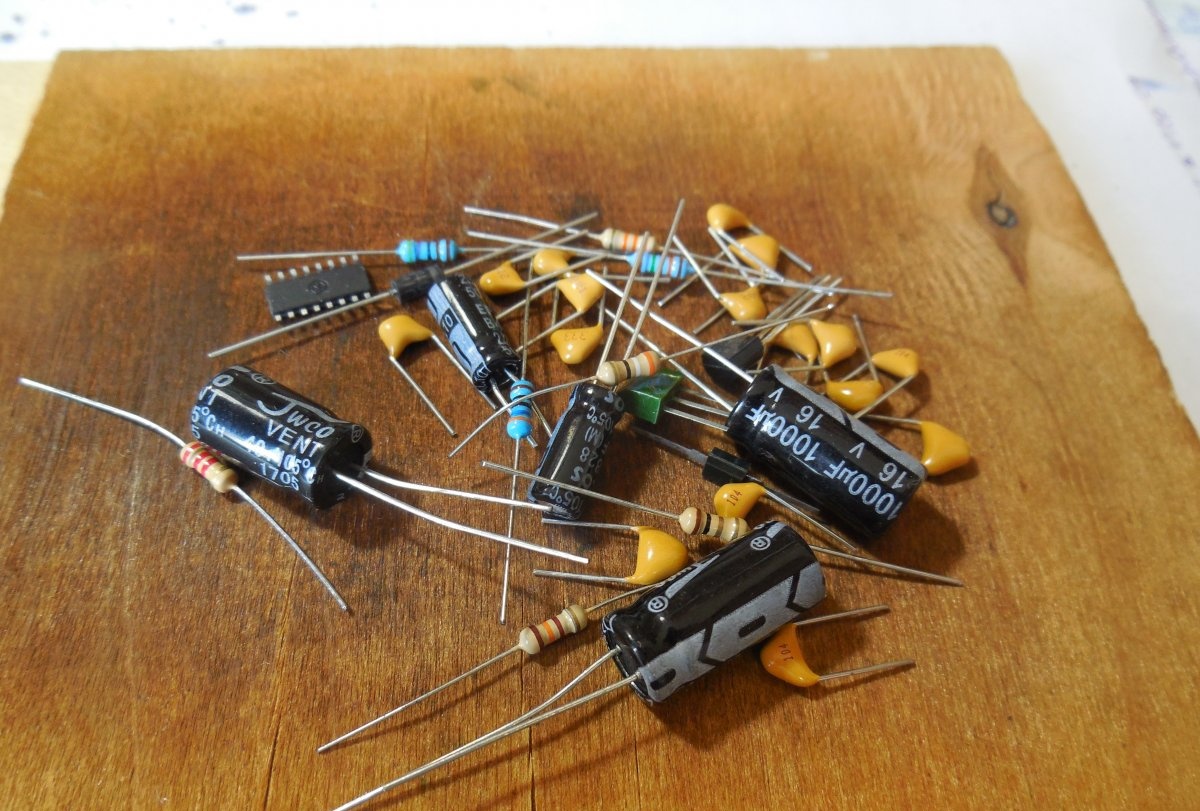
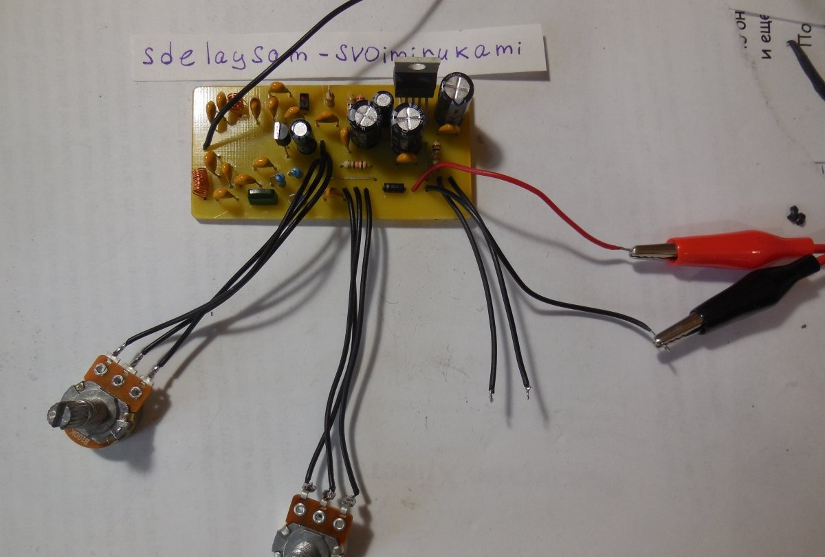
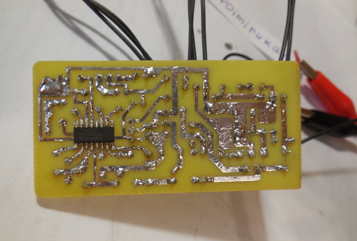
First, we solder in small parts - resistors, capacitors, varicaps, transistors, microcircuits. Then large electrolytic capacitors and wound coils. When soldering the coil, the varnish insulation at its ends should be stripped. The simplest, but nevertheless effective antenna is a piece of wire about 70 cm long, located vertically, soldered directly to the board. After sealing all the parts, we connect the controls - potentiometers, wires for power supply, wires for connecting speakers/headphones. We check the correct installation, wash off any remaining flux from the board, and the assembly is complete.
First startup and setup
When first turned on, the volume control should be in the minimum position, pulling the amplifier's input to ground. We apply power, then gradually increase the volume - a characteristic noise should immediately appear in the speaker. Then slowly rotate the potentiometer until the noise changes to a signal from a radio station. Now it remains to adjust the frequency adjustment limits so that by rotating the potentiometer you can catch all stations in the range of 88-108 MHz.This can be done by stretching/compressing the turns of coil L1, as well as changing the capacitance of capacitor C8. When changing the capacitance, the overall width of the receiver's adjustment range will also change; it should be about 20 MHz (the "distance" between 88 and 108 MHz). Happy building!