Let's consider creating a tracked vehicle with a fairly basic design that can be assembled in literally a couple of evenings. The entire structure can be roughly divided into two parts - the tracked chassis and the electrical part, which will provide remote control of the machine from the remote control.
Chassis manufacturing
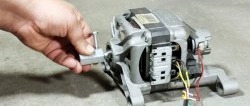
Not many materials will be needed: the tracks will be driven by a pair of geared motors, the basis of the entire structure will be a small piece of thick plywood, and you will also need several plastic wheels on which the tracks will rotate. For the machine you can use almost any suitable sized geared motors, the “yellow” ones are ideal, which can be found in many radio parts stores, or you can buy them on Ali, the gearbox in them gives a gear ratio of 1:48, which for this case is the most optimal value .

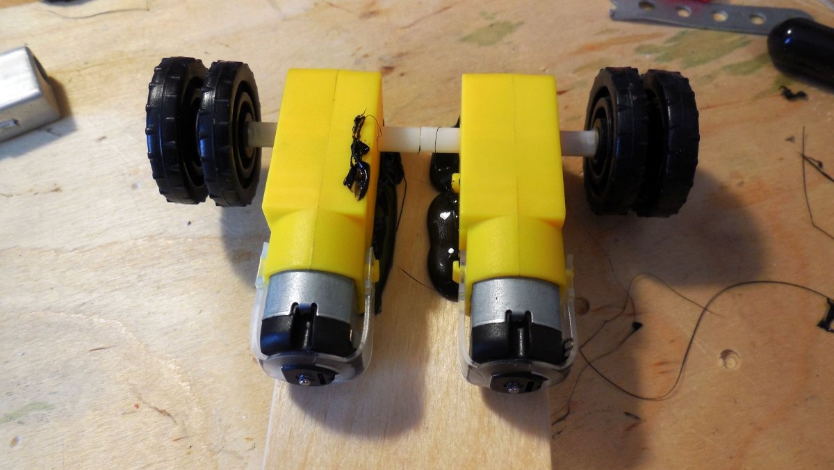
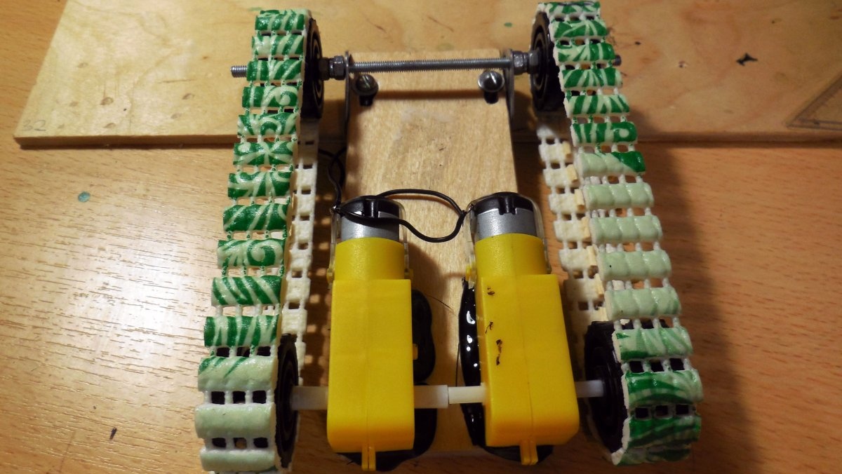
Each gearbox has output to two shafts, on opposite sides of the body - for the tracked chassis, only one shaft from each motor will be used, the second can be removed completely or left in case these motors are still needed in other projects.It is necessary to fasten the wheels to the shafts - the easiest way to do this is to screw a self-tapping screw into the shaft itself (it is hollow inside), so the wheels will clamp well. For additional fixation and to prevent the self-tapping screw from unwinding, you can generously lubricate the joint with glue. Please note that the wheel is double - a gap of approximately 3-4 mm is made between each wheel; in the future, the caterpillar will be fixed with it.

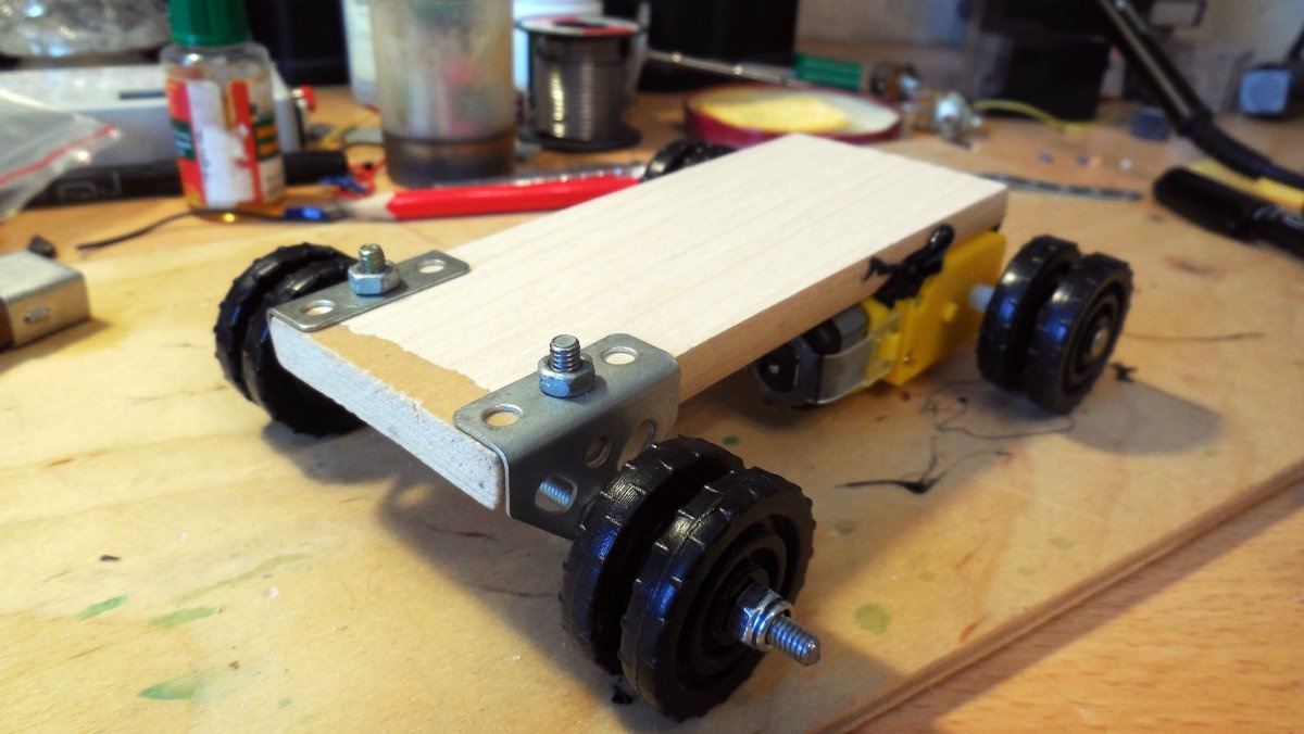
The motors are mounted on a piece of durable plywood; its size can be chosen arbitrarily, depending on the desired size of the machine. These gearmotors do not provide any convenient places for fastening, so I fixed them with hot glue - good glue sticks provide excellent connection quality, as experience has shown.
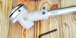
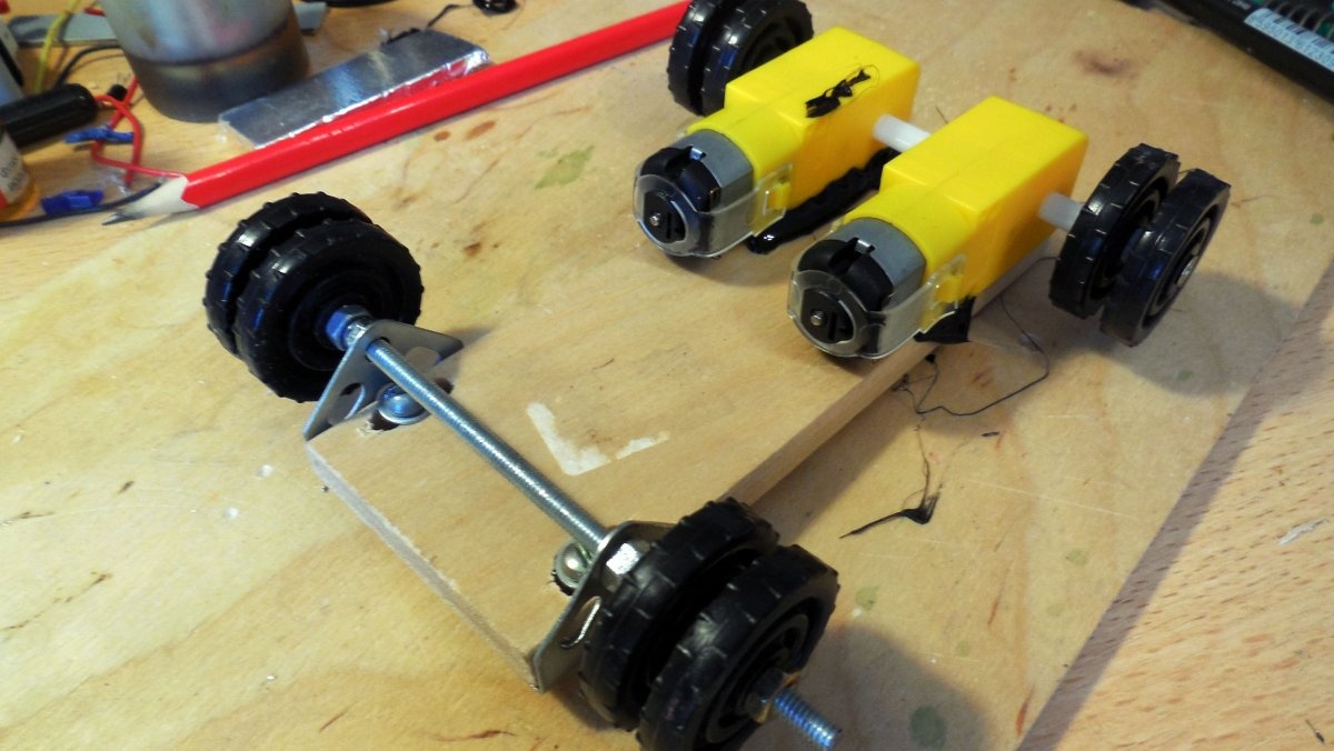
Next, on the opposite side of the motors, you need to secure the corners for the axle of the front wheels. To do this, I highly recommend using parts from a children's iron construction set - there you can find ready-made corners with holes. When drilling a hole in plywood, you need to take into account that in the future you will need to adjust the tension of the tracks, so you need to drill a series of holes approximately 1-1.5 cm long, which are then connected into one oblong slot. This way, the entire front axle will move back and forth, bolted into place.

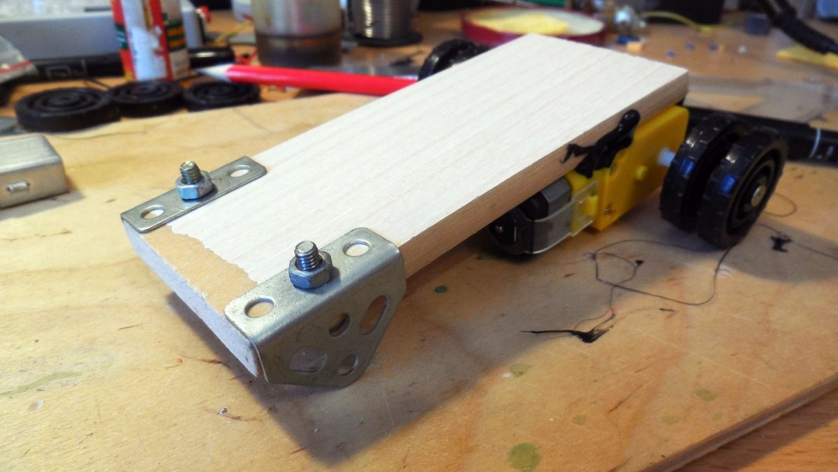
A pin is threaded into the holes in the corners; it is convenient to use M4, it provides sufficient rigidity and at the same time fits the holes in the parts of the iron constructor. The stud must be firmly secured to the corners; it is convenient to use locking nuts for this; they will not unscrew on their own when the machine starts moving. The same double wheels are installed on the sides as on the rear, with exactly the same clearance.The wheels must rotate freely on the axle; this can be ensured with the same locking nuts. Please note that the left and right wheels must rotate independently of each other. I took these wheels from the same iron construction set, but you can cut similar ones from plastic or thick cardboard, if you fold it in several layers and glue it together.
Making caterpillars
It’s hard to imagine, however, excellent tracks with good traction can be made from a PVC bath mat, which can be found in almost any hardware store. Such a rug consists of many flexible “strips” that are connected to each other by parallel threads, which is what is needed to create a caterpillar. A strip 1.5-2 cm wide is cut from the mat; it should be equal to the width of the wheels used.

Then you need to apply the tape to the wheels attached to the chassis and cut it to the required length, then the ends of the tape are glued together with superglue. After the glue has dried, you can try the caterpillar on the chassis and even turn on the motor - the caterpillar will rotate, but will quickly fall off the wheels.
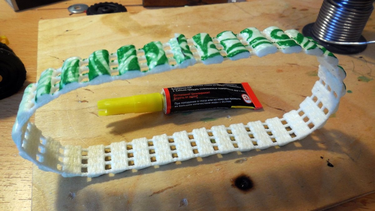

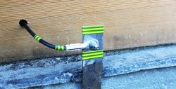
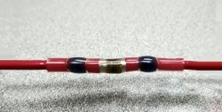
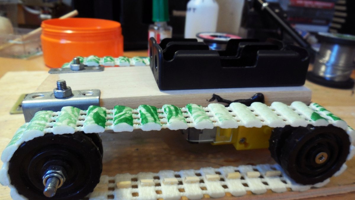
To ensure that the caterpillar does not fall off the wheels, even when the future vehicle runs over obstacles, you need to make convex stops in the center of the caterpillar. When rotating, they will fall into the gap between the wheels, preventing the track from coming off. There are many ways to make such stops; I decided to glue matches to each “step” of the caterpillar; as experience has shown, this method turned out to work and with sufficient tension the caterpillar did not fall off at all. The matches are cut into pieces 5-6 mm long and glued, as shown in the photo below, the same superglue is used - it ensures good bonding strength with the PVC mat material.


All the same actions need to be done with the second caterpillar.After gluing the matches, the tracks can be considered ready - now they are relying on the chassis and they can already check how the future car will drive by applying voltage from the battery directly to both motors. If necessary, you need to adjust the tension force - a track that is too weak will rotate or fall off, and a track that is too tight will rotate tightly, putting additional stress on the motor.

Electrical part
In the electrical part, you will need several boards at once: receiver and transmitter boards for transmitting commands from the remote control, boost converters to power the motors, as well as “bridge” boards to allow each motor to rotate in both directions. The general scheme is as follows - the transmitter board will be installed in the remote control, the receiver board on the chassis of the machine. Boost converters convert the voltage from the batteries (3.7 - 4.2 volts) to a level of 7-8 volts, from which the motors will be powered. If the motors develop sufficient speed directly from the battery, then converters do not need to be installed. The rotation of the motors will be controlled by bridge circuits - special circuits with field-effect transistors that can supply the output with a voltage of either one polarity or the other, depending on which input (in 1 or in 2) the control signal from the receiver board will receive. First, let's look at the transmitter and receiver circuits, they are presented below respectively.

To be precise, these circuits are called an encoder and decoder, and the receiver and transmitter are ready-made RX-TX modules at a frequency of 433 MHz, which can easily be bought on Ali or many radio parts stores - Each of the modules has three contacts for connection - power plus, minus, as well as a DATA contact for sending or receiving data.The simple circuits presented above provide a data transfer protocol, allowing you to process 5 button presses. To control the machine you will need only 4 channels (forward, backward, right, left), so the 5th channel remains free and can be used for any purpose, for example, turning the headlights on and off. The TXD and RXD contacts in the diagrams are connected to the DATA contacts of the transmitter and receiver, respectively; otherwise, the diagrams are simple and hardly require explanation. The supply voltage of the circuits themselves is 3.5-5 volts, however, if you install 78l05 stabilizers (they are indicated in the diagrams), you can power them from a voltage of 7 or more volts. Printed circuit boards provide both power options; you just need to install jumpers in the right places. For use in a machine, both the receiver and the transmitter can be powered directly from batteries without stabilizers. Each of the circuits has a microcontroller - it must be flashed with the appropriate firmware; the firmware is in the archive along with the board files.
Archive with schematics, firmware and boards:
Making the remote control
As one option, you can use a ready-made remote control from some broken/unnecessary radio-controlled toy, if there is enough space inside it to install the encoder board. Or you can make your own remote control, as I did. As a base, I used another piece of plywood, mounting on it a holder for an 18650 battery, an encoder board with a receiver module, as well as 4 buttons, arranging them for maximum ease of control.Please note that the encoder board already contains mounting spaces for buttons on the board - their installation is not necessary, except to check functionality after assembly. The operating buttons are removed from the board on wires, as in the photographs below.


Mounting electronics on the chassis
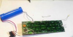
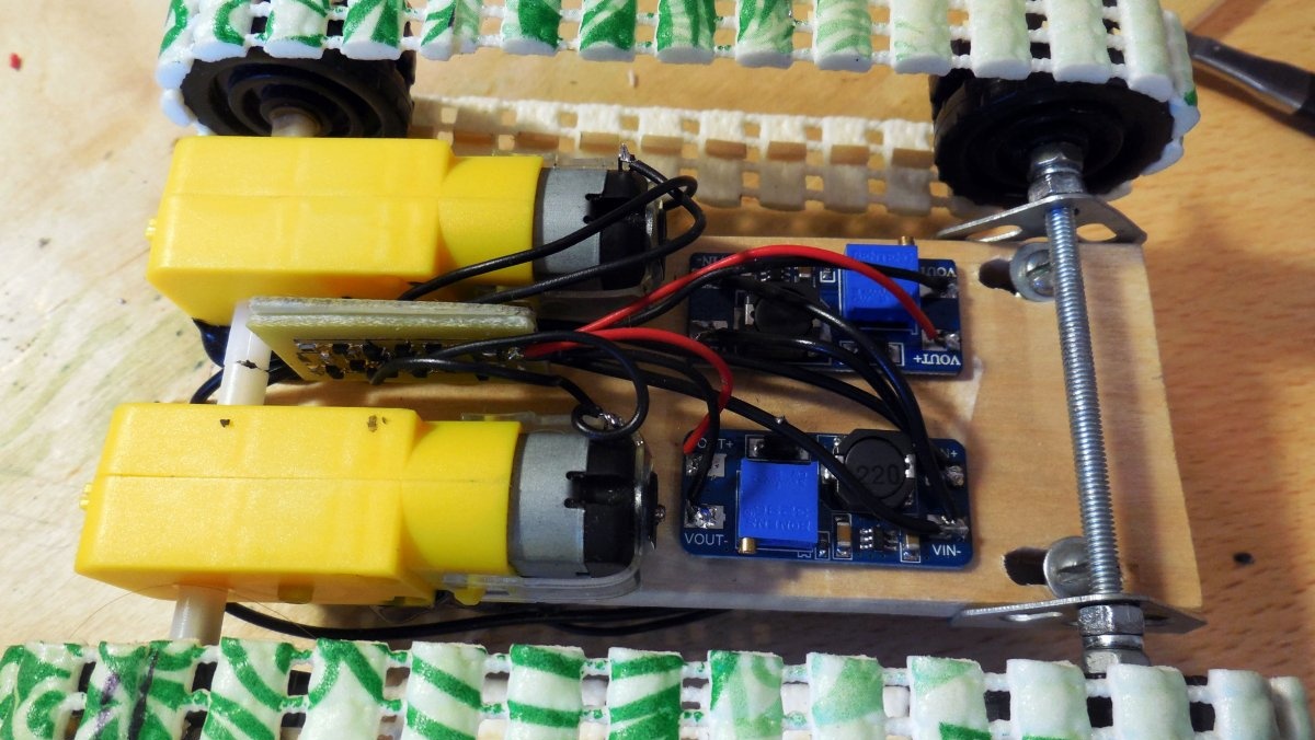
On the chassis itself, therefore, in addition to the decoder board with the receiver module, two “bridge” boards and two converters will be installed. The good thing about using two converters, one for each motor, is that you can adjust the speed of each track separately. Although the gearmotors are identical, they still have some variation in parameters, so even with the same supply voltage they can produce slightly different speeds; by adjusting the voltage at the output of the converters, you can achieve the same speed. A distortion in speeds, even a small one, will lead to the fact that the car will not drive straight forward, but with a slight turn. Below in the photo you can see all the boards required for installation on the chassis.

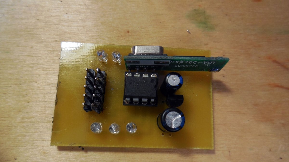
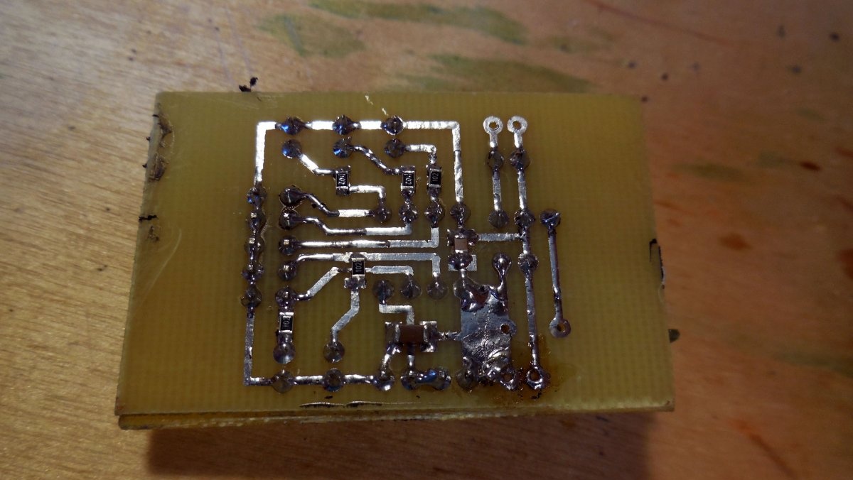
Detailed photo of the decoder board. Please note that it, like the encoder board, has several additional power supply capacitors - they will definitely not be superfluous in devices with microcontrollers.
Bridge circuit assembly
It would seem why some kind of bridge circuit is needed, because it is enough just to apply voltage to the motors using a key. And it really is not needed if the car does not require reverse gear - and practice shows that without it it is not at all interesting. Thus, it is necessary to assemble a small additional circuit that will provide a polarity change for the motor. The polarity changes - the direction of movement changes.

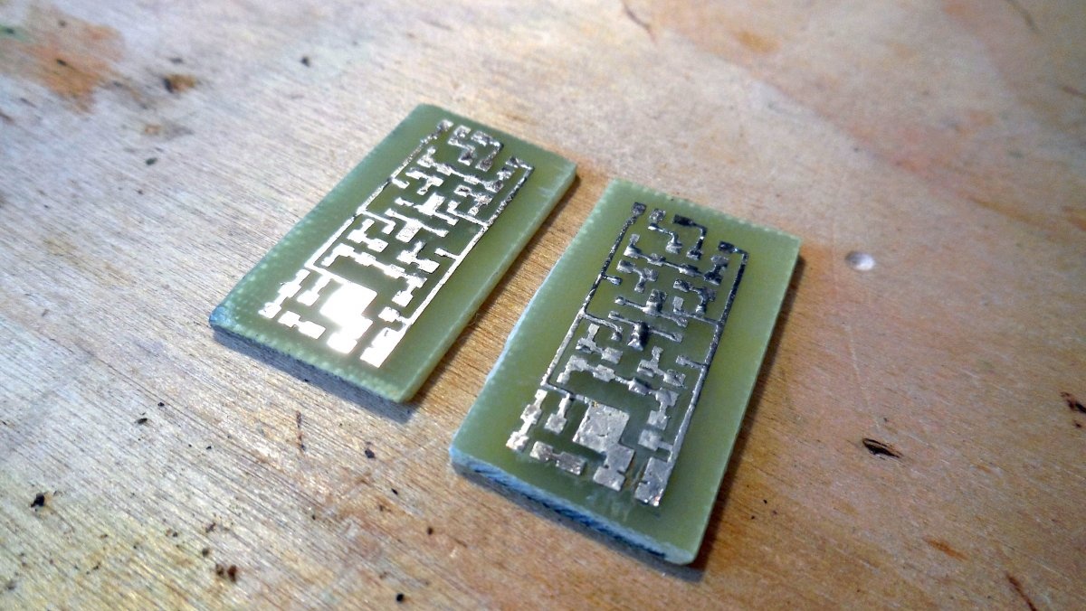
The motor is connected to this circuit, and it also contains two inputs - in1 and in2, apply 3-5 volts to one input - the motor rotates in one direction, apply 3-5 volts to the other - the motor rotates in the other direction. If voltage is not supplied to either input, or is applied to both inputs at once, the motor does not rotate, this is the simple logic of operation. There are 4 field-effect transistors in the circuit that will switch the motor, so they must be designed for a sufficiently high current. Two of them are N-channel, you can use AO3400, the other two are P-channel, AO3401 is suitable. Also on the diagram there are two bipolar NPN transistors; BC847 or any other similar ones will do. In order not to take up much space on the chassis, I recommend assembling this circuit using SMD components. Diodes - any you like, for example, 1N4148W. The power input of this circuit (designated as 12 V) is supplied with voltage from the converter. Please note that the circuit must be assembled in two copies - for the left and right motors, respectively, they will be powered from one and from the second converter. Photos of the assembled boards are below.

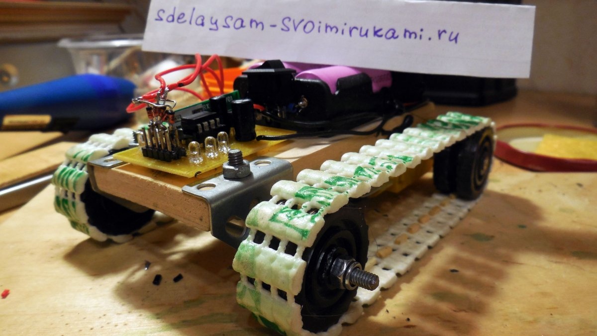
Now you can proceed directly to the installation - and the first step is to install a pair of holders for 18650 batteries on the top of the chassis; all the electronics will be powered from them; the batteries are connected in parallel.
In front of the batteries, in the front part, a decoder board is installed; it can be immediately connected via a switch to the contacts of the holders. For convenience, this board additionally has 5 LEDs – when you press the remote control keys, the corresponding ones will light up LEDs.

A pair of converters and a pair of bridge boards are attached to the lower part, under the chassis.Everything is immediately connected by wires - the inputs of the converters through a switch to the holders, the outputs of the converters to power the bridge boards, and the outputs of the bridges, in turn, to the motors. It should be taken into account that motors under load can consume quite a large current; accordingly, at the input of the converters, the current consumed will be approximately 2 times greater and at some moments can reach 1-1.5 amperes, so you need to supply power with fairly thick wires.

The last, final stage of assembly remains - you need to connect the decoder outputs (4 out of 5 outputs will be used) to the bridge inputs (in1, in2), so that when you press certain keys on the remote control, the machine reacts in the desired way. Namely:
- Pressing “forward” - both motors rotate in the same direction.
- Pressing “back” - both motors rotate in the opposite direction.
- Pressing “right” - the left motor rotates forward, the right motor rotates backward, while the machine turns clockwise in place.
- Pressing “left” - the right motor rotates backward, the left motor rotates forward, the machine turns counterclockwise.
- Simultaneously pressing “forward” and “right” - the left motor rotates forward, the right one stands still, thus a smooth turn occurs.
- Simultaneously pressing “forward” and “left” is similar, but in the other direction.
To implement such logic, it is necessary to connect the decoder outputs to the bridge inputs as shown below.
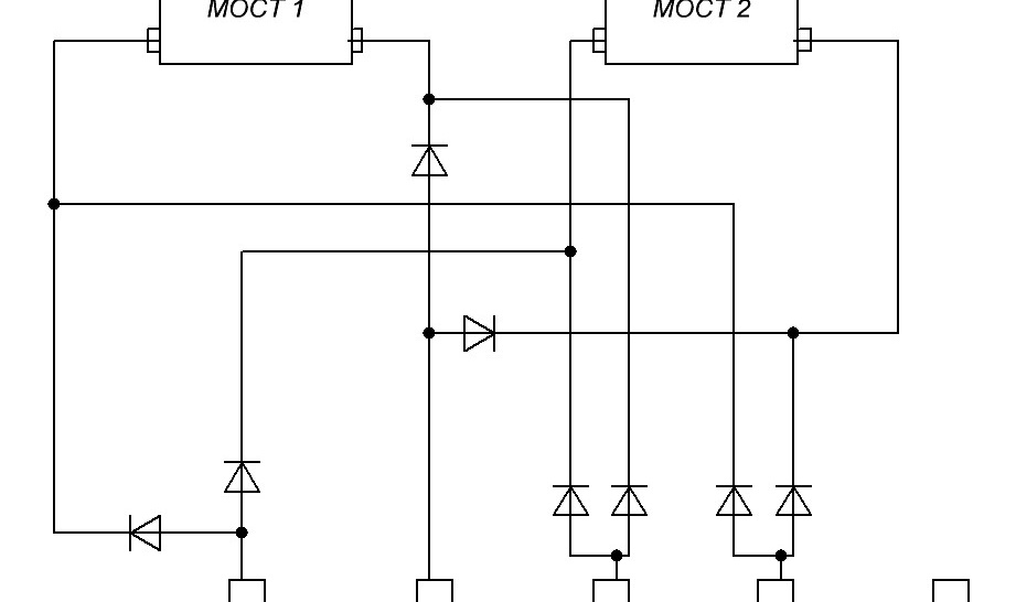
The decoder outputs are shown below, with one of them free and can be used for other actions. The diodes here can be used the same 1N4148, soldered by surface mounting directly at the decoder outputs.
Tests
At this point, the assembly of the machine is completed, you can insert the batteries and check the operation. In this case, it would not be amiss to check the current consumption - in the absence of commands from the remote control, it should be small, about several tens of mA. The range of the remote control will depend on the receiver and transmitter modules used - most often they provide a reliable reception area of about 20-30 meters in urban conditions, which is quite enough to control the machine. Antennas will help to significantly increase the range; you can take pieces of copper wire 17 cm long (for a frequency of 433 MHz) and solder them to the “ant” contacts of the modules.


Thus, the result is a very entertaining toy for children and adults - the PVC mat tracks provide excellent grip on any surface, so the machine can easily overcome obstacles. The advantages of the tracked version also include ease of control - there is no need to install additional steering mechanisms, all control occurs only by changing the direction of rotation of the tracks. The disadvantage of the described chassis design can be called the small “ground clearance” - the motors are located under the bottom and take up quite a lot of space there, however, this does not interfere with the pleasure of “driving”, and if desired, this disadvantage can be eliminated by adding an additional axle for rear wheels and placing the motors on top. Happy building!