Do it yourself
Life hacks, master classes, useful tips, recipes.
home » Electronics » DIY power supply » Car inverter 12-220V
I bought myself a car six months ago. I will not describe all the modernizations made to improve it, I will focus on only one. This is a 12-220V inverter for powering consumer electronics from the vehicle's on-board network.
Of course, you could buy it in a store for $25-30, but I was confused by their power. To power even a laptop, the 0.5-1 ampere current that most car inverters produce is clearly not enough.

Choosing a circuit diagram.
By nature, I am a lazy person, so I decided not to “reinvent the wheel”, but to search the Internet for similar designs, and adapt the circuit of one of them for my own crafts. Time was very pressing, so simplicity and the absence of expensive spare parts were the priority.

inverter circuit


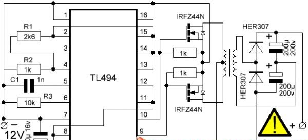
On one of the forums, a simple circuit was chosen using the common PWM controller TL494. The disadvantage of this circuit is that it produces a rectangular voltage of 220 V at the output, but for pulsed power circuits this is not critical.

Selection of parts.
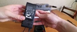
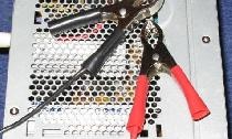
The circuit was chosen because almost all the parts could be taken from a computer power supply. For me this was very critical, because the nearest specialized store is more than 150 km away.

for the device


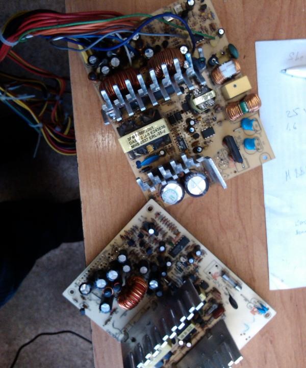
Output capacitors, resistors, and the microcircuit itself were removed from a pair of faulty power supplies of 250 and 350 W.
The difficulty arose only with high-frequency diodes for converting the voltage at the output of the step-up transformer, but here old supplies saved me. The characteristics of the KD2999V suited me quite well.

Assembly of the finished device.

I had to assemble the device within a couple of hours after work, because a long trip was planned.
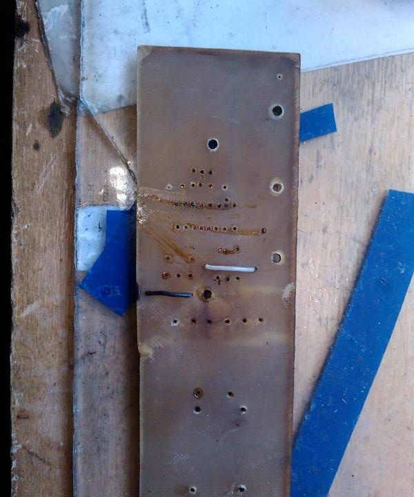
Since time was very limited, I simply did not look for additional materials and tools. I used only what was at hand. Again, due to speed, I did not use the printed circuit board samples provided on the forums. In 30 minutes, we designed our own printed circuit board on a piece of paper, and its design was transferred to the PCB.
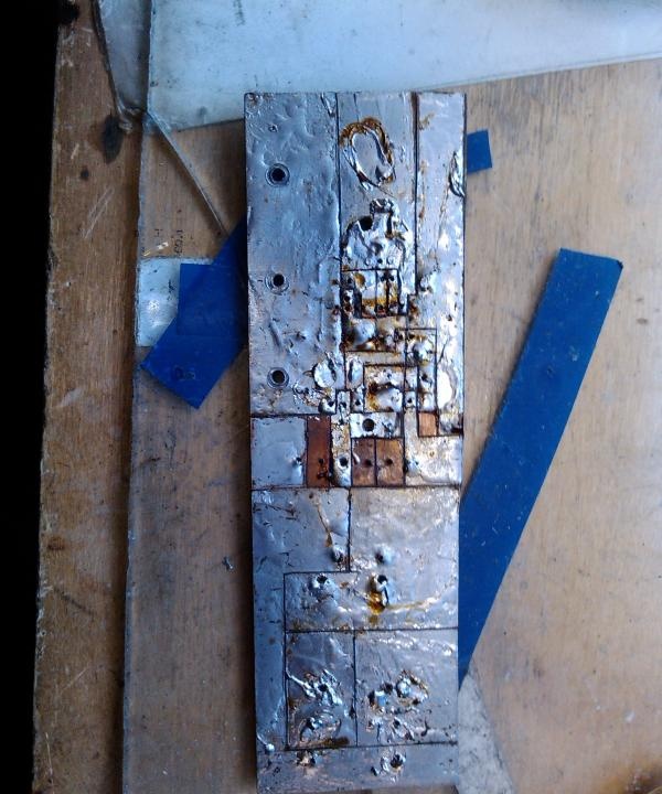
Using a scalpel, one of the foil layers was removed. On the remaining layer, deep grooves were drawn along the applied lines. Using curved tweezers, it turned out to be the most convenient, the grooves were deepened to the non-conducting layer. At the places where the parts were installed using an awl, it was not included in the photo, holes were made.

we fasten the elements


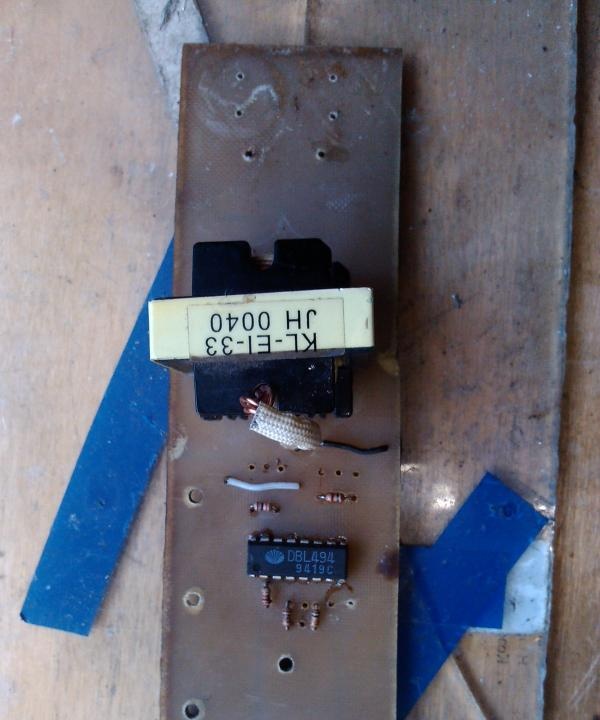
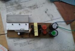
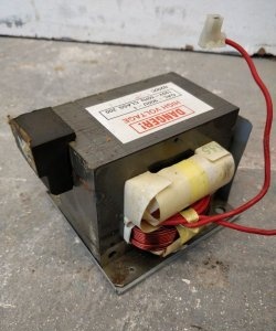
I started the assembly by installing a transformer, I used a step-down one of the blocks, I simply turned it over and instead of lowering the voltage from 400 V to 12 V, it raised it from 12 V to 268 V. By replacing resistors R3 and capacitor C1, it was possible to reduce the output voltage to 220 V, but further experiments showed that this should not be done.
After the transformer, in order of decreasing size, I installed the remaining spare parts.

pay

inverter ready

board below


It was decided to install field-effect transistors on elongated inputs so that they are easier to attach to the cooling radiator.

inverter bottom view


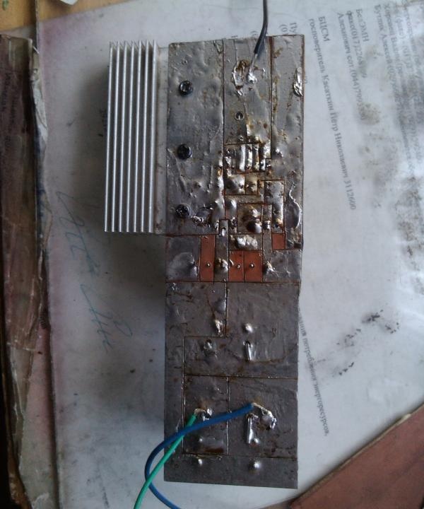
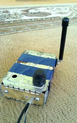
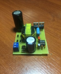
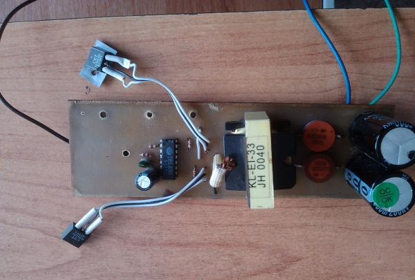
The end result is this device:

car inverter


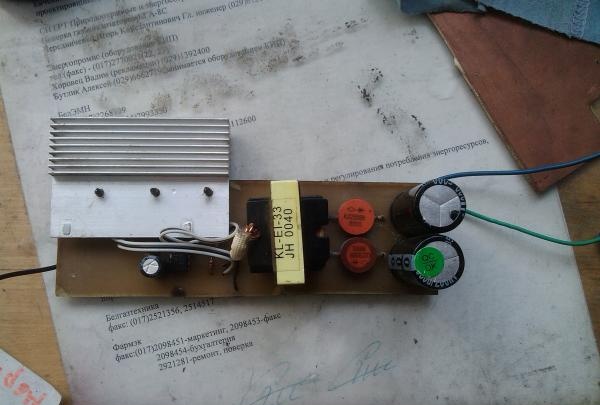
All that remains is the finishing touch - attaching the radiator. There are 4 holes visible on the board, although there are only 3 self-tapping screws; it was just during the assembly process that it was decided to slightly change the position of the radiator for a better appearance. After final assembly this is what we got:

Tests.
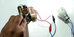
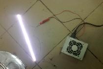
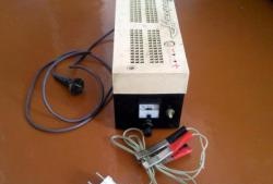
There was no time to specifically test the device; it was simply connected to the battery from an uninterruptible power supply. A load in the form of a 30 W light bulb was connected to the output. After it caught fire, the device was simply thrown into my backpack, and I went on a business trip for 2 weeks.
In 2 weeks, the device never failed. Various devices were powered from it. When measured with a multimeter, the maximum current obtained reached 2.7 A.
come back
Comment
  • bowtiesmilelaughingblushsmileyrelaxed relaxedsmirk
    heart_eyeskissing_heartkissing_closed_eyesflushedrelievedsatisfiedgrin
    winkstuck_out_tongue_winking_eyestuck_out_tongue_closed_eyesgrinningkissingstuck_out_tonguesleeping
    worriedfrowninganguishedopen_mouthgrimacingconfusedhushed
    expressionlessunamusedsweat_smilesweatdisappointed_relievedwearypassive
    disappointedconfoundedfearfulcold_sweatperseverecrysob
    joyastonishedscreamtired_faceangryragetriumph
    sleepyyummasksunglassesdizzy_faceimpsmiling_imp
    neutral_faceno_mouthinnocent
5+two=
Comments (24)
  1. Vasya was here
    #1 Vasya was here Guests 14 April 2014 02:45
    3
    Why transform 12 to 220, then 220 to 18? Blocking generator with a coefficient of 1.5 + zener diode and filter capacitor. 12 at 18...that's it. :winked:
  2. Mistiword
    #2 Mistiword Guests 19 October 2014 19:26
    4
    My voltmeter constantly shows 127V
    1. Valdemar
      #3 Valdemar Guests 8 July 2018 18:21
      0
      So everything is correct, the output is constant voltage. See diagram.
  3. timerleng
    #4 timerleng Guests November 7, 2014 09:44
    2
    I assembled everything according to the diagram, everything works great, thanks to the author for the article
  4. Kettle
    #5 Kettle Guests November 19, 2014 11:10
    4
    Sorry, I don’t understand where the fourth wire is?
  5. Ruslan
    #6 Ruslan Guests December 21, 2014 16:32
    4
    What is the power of this unit?
  6. nebbes
    #7 nebbes Guests January 10, 2015 11:43
    2
    Quote: Ruslan
    What is the power of this unit?

    The author wrote: When measured with a multimeter, the maximum current obtained reached 2.7 A.
    it turns out that the power is 2.7A*220V=594W
    1. Valdemar
      #8 Valdemar Guests 8 July 2018 18:16
      3
      it turns out that the power is 2.7A*220V=594W
      ---------------
      In this device, the output current cannot be 2.7 A, because... The current consumption from the battery must be at least 220A!!!! This is at an efficiency of 1. The author was mistaken, this is the current consumption from the battery, and accordingly, the output current in the BEST case will be about 0.145 A.
      1. Ignoramus.
        #9 Ignoramus. Guests 20 January 2019 14:19
        1
        Well, probably not 220A, but about 50A. If 594W is divided by 12V. then you get 49.5A with efficiency = 1
  7. Dmitriy
    #10 Dmitriy Guests 14 January 2015 15:00
    5
    Hello. I really want to build this device. There are several questions.
    Is a 220 m 200v capacitor suitable instead of a 200 m 200v capacitor?
    Instead of a 500 16v capacitor, would a 470m 16v be suitable?
    Will any transformer from the computer's power supply be suitable, or is there a difference? Mine has 2 legs on one side and 6 on the other, which ones are used?
    Please, help. Thank you very much in advance!
  8. Dima
    #11 Dima Guests 30 March 2015 22:10
    4
    NNda... Picasso is straight. Transistors must NOT be hung on long wires. KD2999V diodes do not pass through reverse voltage (up to 200V), but 400V is needed. Nothing will work with this installation; you need a printed circuit board.Is there a fuse? Otherwise this masterpiece will cause a fire. Instead of diodes, FR107 (1A, 1kV), FR207(2A), FR307 (3A) will be used. The first two are found in computer power supplies, the third is not a problem to buy.
  9. Sergey
    #12 Sergey Guests 28 May 2015 18:08
    2
    Current consumption frozen?
  10. Igor Karpovich
    #13 Igor Karpovich Guests December 1, 2015 09:58
    0
    The payment is no good.

Arc discharge | Do it yourself

How to make a simple digital TV antenna from an aluminum can

Master class on making a three-dimensional heart | Do it yourself

Beautiful and tender card | Do it yourself

«Do it yourself - with your own hands» - a site of interesting homemade products made from scrap materials and items at home. Step-by-step master classes with photos and descriptions, technologies, life hacks - everything a real master or just a craftsman needs for needlework. Crafts of any complexity, a large selection of directions and ideas for creativity.

We recommend reading

Washing machine error codes