Hello, dear ladies and gentlemen!
On this page I will briefly tell you how to convert a personal computer power supply into a charger for car (and other) batteries with your own hands.
A charger for car batteries must have the following properties: the maximum voltage supplied to the battery is no more than 14.4V, the maximum charging current is determined by the capabilities of the device itself. This is the charging method that is implemented on board the car (from the generator) in the normal operating mode of the car’s electrical system.
However, in contrast to the materials from this article, I chose the concept of maximum simplicity of modifications without the use of homemade printed circuit boards, transistors and other “bells and whistles”.
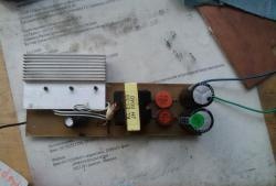
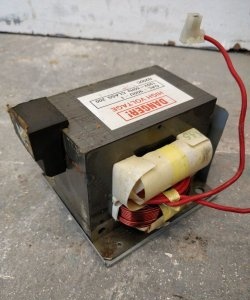
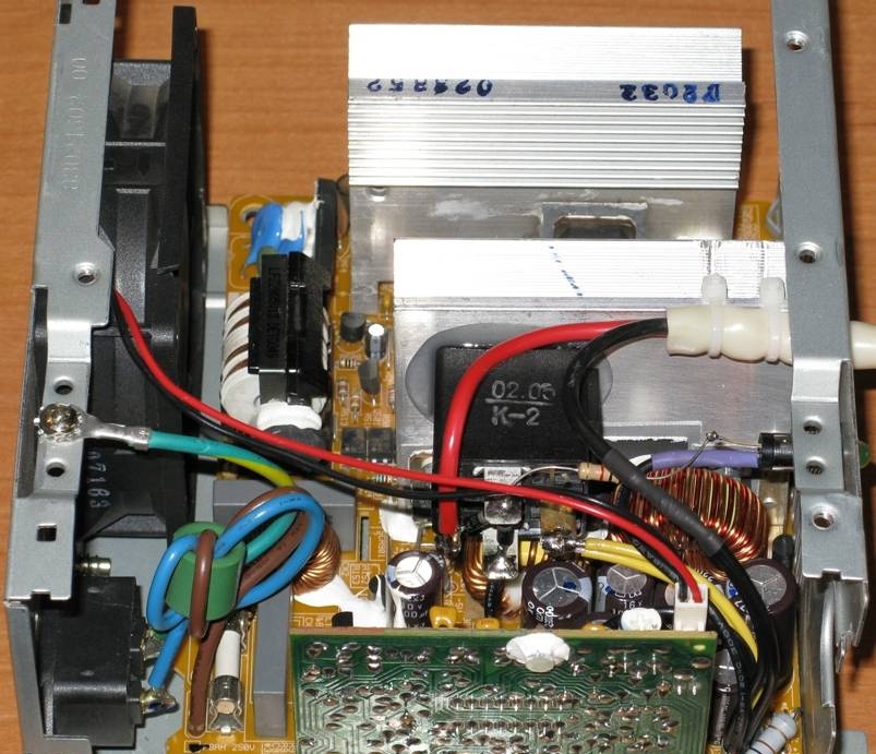
A friend gave me the power supply for the conversion; he himself found it somewhere at his work.From the inscription on the label it was possible to make out that the total power of this power supply is 230W, but the 12V channel can consume a current of no more than 8A. Having opened this power supply, I discovered that it does not contain a chip with the numbers “494” (as described in the article above), and its basis is the UC3843 chip. However, this microcircuit is not included according to a standard circuit and is used only as a pulse generator and a power transistor driver with an overcurrent protection function, and the functions of the voltage regulator on the output channels of the power supply are assigned to the TL431 microcircuit installed on an additional board:
A trimming resistor is installed on the same additional board, which allows you to adjust the output voltage in a narrow range.
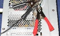
So, to convert this power supply into a charger, you first need to remove all unnecessary things. The redundant ones are:
1. 220/110V switch with its wires. These wires just need to be unsoldered from the board. At the same time, our unit will always operate on 220V voltage, which eliminates the danger of burning it if this switch is accidentally switched to the 110V position;
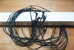
2. All output wires, with the exception of one bundle of black wires (4 wires in a bundle) are 0V or “common”, and one bundle of yellow wires (2 wires in a bundle) are “+”.
Now we need to make sure that our unit always works if it is connected to the network (by default, it only works if the necessary wires in the output wire bundle are short-circuited), and also eliminate the overvoltage protection, which turns off the unit if the output voltage becomes HIGHER than a certain specified one limit.This needs to be done because we need to get 14.4V at the output (instead of 12), which is perceived by the built-in protections of the unit as overvoltage and it turns off.
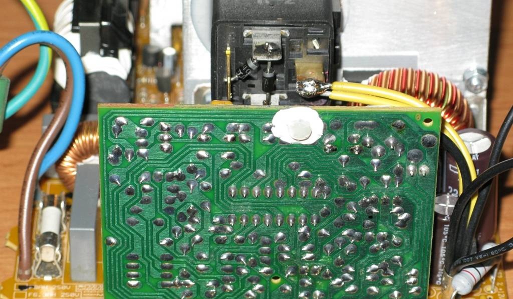
As it turned out, both the “on-off” signal and the overvoltage protection action signal pass through the same optocoupler, of which there are only three - they connect the output (low-voltage) and input (high-voltage) parts of the power supply. So, in order for the unit to always work and be insensitive to output overvoltages, it is necessary to close the contacts of the desired optocoupler with a solder jumper (i.e., the state of this optocoupler will be “always on”):
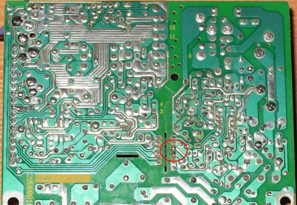
Now the power supply will always work when it is connected to the network and no matter what voltage we set at its output.
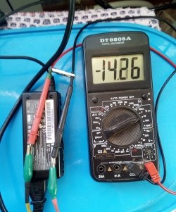
Next, you should set the output voltage at the output of the block, where there was previously 12V, to 14.4V (at idle). Since only by rotating the trimmer resistor installed on the additional board of the power supply, it is not possible to set the output to 14.4V (it only allows you to make something somewhere around 13V), it is necessary to replace the resistor connected in series with the trimmer with a slightly smaller resistor nominal value, namely 2.7 kOhm:
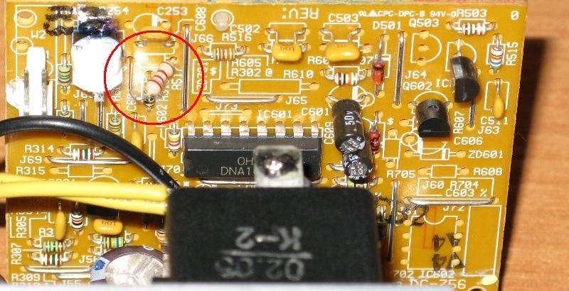
Now the output voltage setting range has shifted upward and it has become possible to set the output to 14.4V.
Then, you need to remove the transistor located next to the TL431 chip. The purpose of this transistor is unknown, but it is turned on in such a way that it can interfere with the operation of the TL431 microcircuit, that is, prevent the output voltage from stabilizing at a given level. This transistor was located in this place:

Next, in order for the output voltage to be more stable at idle, it is necessary to add a small load to the output of the unit along the +12V channel (which we will have +14.4V) and on the +5V channel (which we do not use). A 200 Ohm 2W resistor is used as a load on the +12V channel (+14.4), and a 68 Ohm 0.5W resistor is used on the +5V channel (not visible in the photo, because it is located behind an additional board):
Only after installing these resistors should the output voltage at idle (no load) be adjusted to 14.4V.
Now it is necessary to limit the output current to a level acceptable for a given power supply (i.e., about 8A). This is achieved by increasing the value of the resistor in the primary circuit of the power transformer, used as an overload sensor. To limit the output current to 8...10A, this resistor must be replaced with a 0.47 Ohm 1 W resistor:
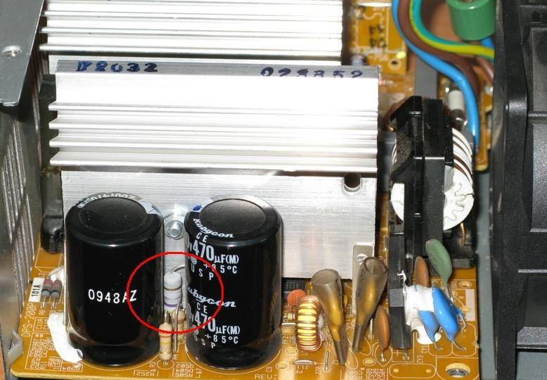
After such a replacement, the output current will not exceed 8...10A even if we short-circuit the output wires.
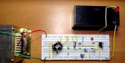
Finally, you need to add a part of the circuit that will protect the unit from connecting the battery with reverse polarity (this is the only “homemade” part of the circuit). To do this, you will need a regular 12V automotive relay (with four contacts) and two 1A diodes (I used 1N4007 diodes). In addition, to indicate that the battery is connected and charging, you will need Light-emitting diode in a housing for installation on a panel (green) and a 1kOhm 0.5W resistor. The scheme should be like this:
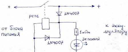
It works as follows: when a battery is connected to the output with the correct polarity, the relay is activated due to the energy remaining in the battery, and after its operation, the battery begins to be charged from the power supply through the closed contact of this relay, which is indicated by a lit Light-emitting diode. A diode connected in parallel with the relay coil is needed to prevent overvoltages on this coil when it is turned off, resulting from self-induction EMF.
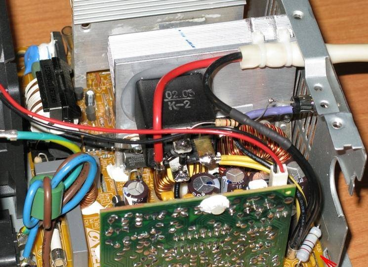
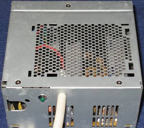
The relay is glued to the heatsink of the power supply using silicone sealant (silicone - because it remains elastic after “drying” and withstands thermal loads well, i.e. compression-expansion during heating and cooling), and after the sealant “dries” onto the relay contacts the remaining components are installed:
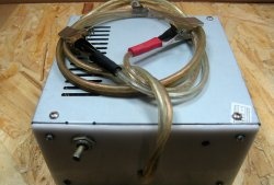
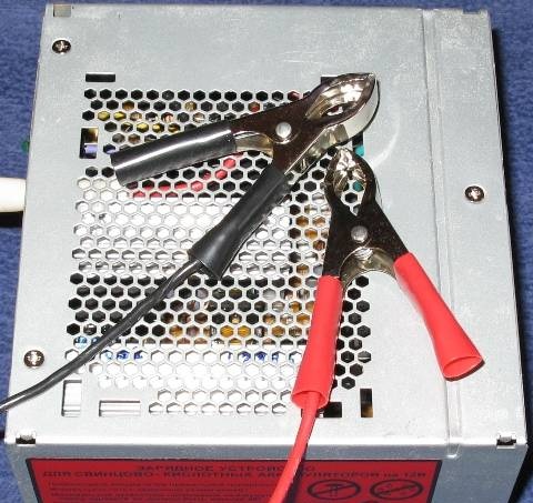
The wires to the battery are flexible, with a cross-section of 2.5mm2, have a length of approximately 1 meter and end in “crocodiles” for connection to the battery. To secure these wires in the device body, two nylon ties are used, threaded through the holes in the radiator (the holes in the radiator must be pre-drilled).
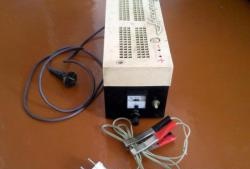
That's all, actually:
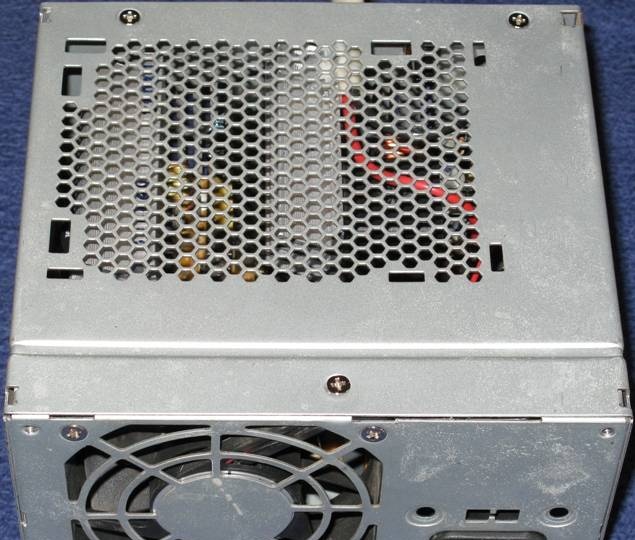
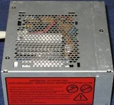
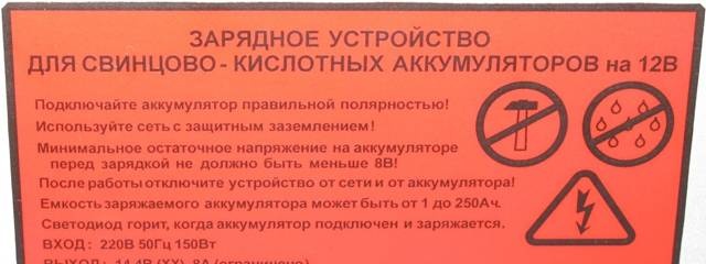
Finally, all labels were removed from the power supply case and a homemade sticker was pasted with the new characteristics of the device:
The disadvantages of the resulting charger include the absence of any indication of the state of charge of the battery, which makes it unclear whether the battery is charged or not? However, in practice it has been established that within a day (24 hours) a regular car battery with a capacity of 55Ah can be fully charged.
The advantages include the fact that with this charger the battery can “stand on charge” for as long as desired and nothing bad will happen - the battery will be charged, but will not “recharge” and will not deteriorate.