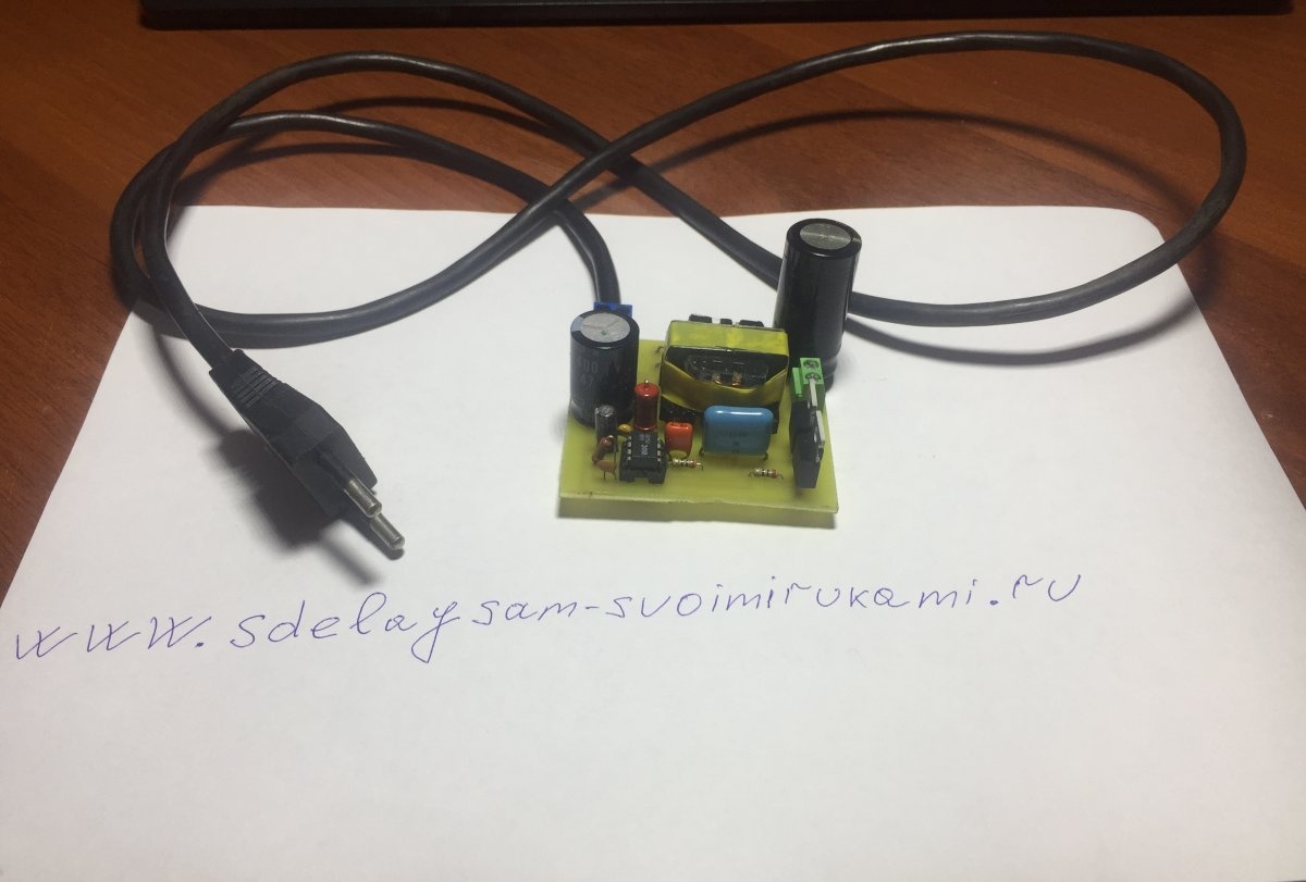
Good day, dear friends, in this article I want to share with you my experience in creating switching power supplies. We will talk about how to assemble a switching power supply using the IR2153 chip with your own hands.
The IR2153 chip is a high-voltage gate driver, many different circuits, power supplies, chargers, etc. are built on it. The supply voltage varies from 10 to 20 volts, the operating current is 5 mA and the operating temperature is up to 125 degrees Celsius.
Beginning radio amateurs are afraid to assemble their first switching power supply, and very often resort to transformer units. At one time I was also apprehensive, but I still pulled myself together and decided to try, especially since there were enough parts to assemble it. Now let's talk a little about the scheme. This is a standard half bridge power supply with IR2153 on board.
Details
Diode bridge at the input 1n4007 or a ready-made diode assembly designed for a current of at least 1 A and a reverse voltage of 1000 V.
Resistor R1 is at least two watts, or 5 watts 24 kOhm, resistor R2 R3 R4 with a power of 0.25 watts.
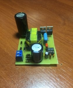
Electrolytic capacitor on the high side 400 volts 47 uF.
Output 35 volts 470 – 1000 uF. Film filter capacitors designed for a voltage of at least 250 V 0.1 - 0.33 µF. Capacitor C5 – 1 nF. Ceramic, ceramic capacitor C6 220 nF, film capacitor C7 220 nF 400 V. Transistor VT1 VT2 N IRF840, transformer from an old computer power supply, diode bridge at the output full of four ultra-fast HER308 diodes or other similar ones.
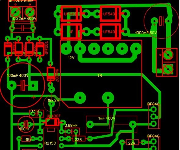
In the archive you can download the circuit and board: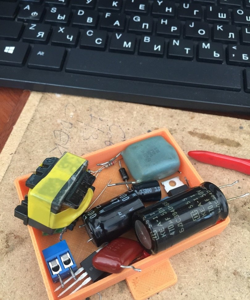
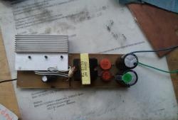
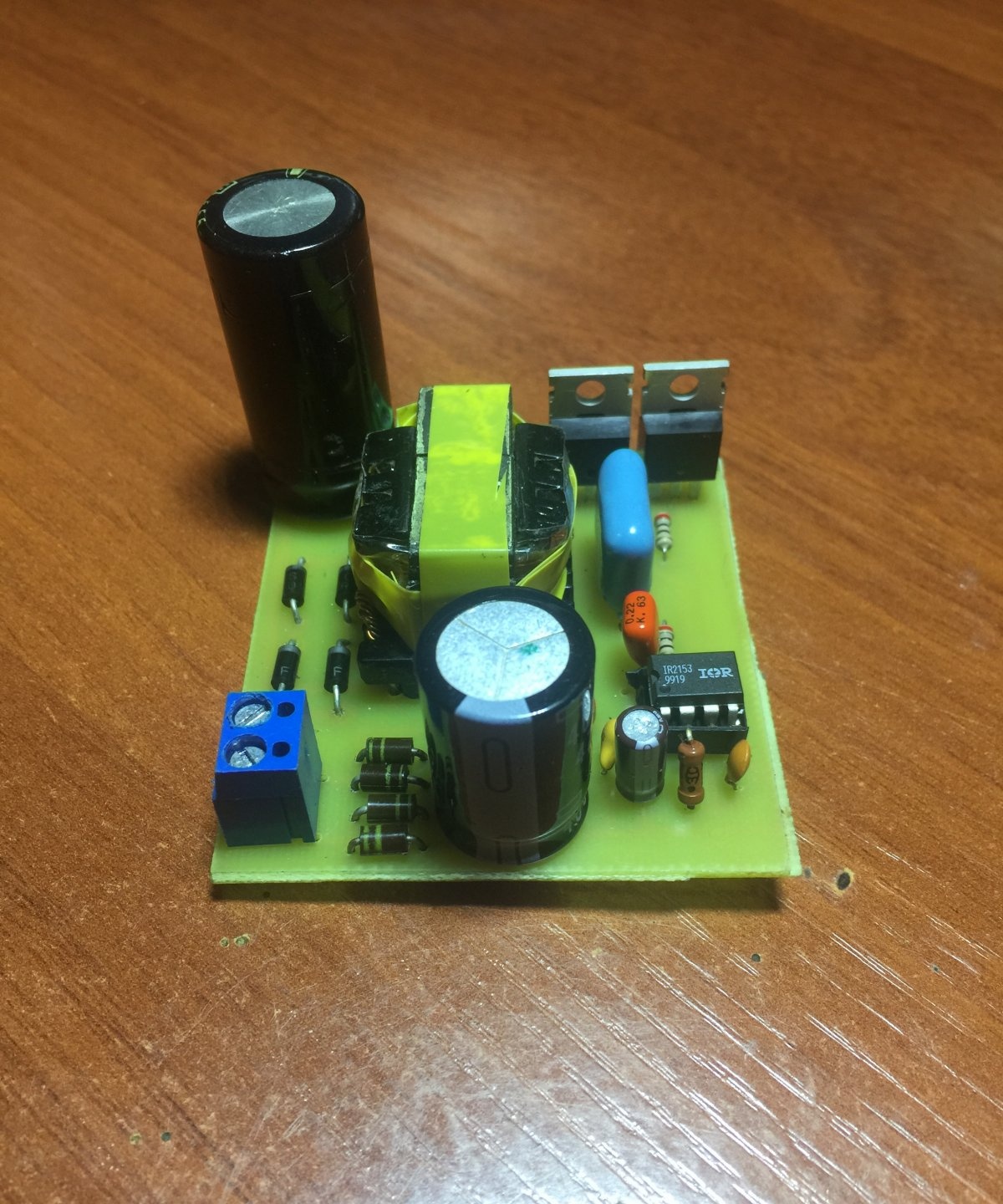
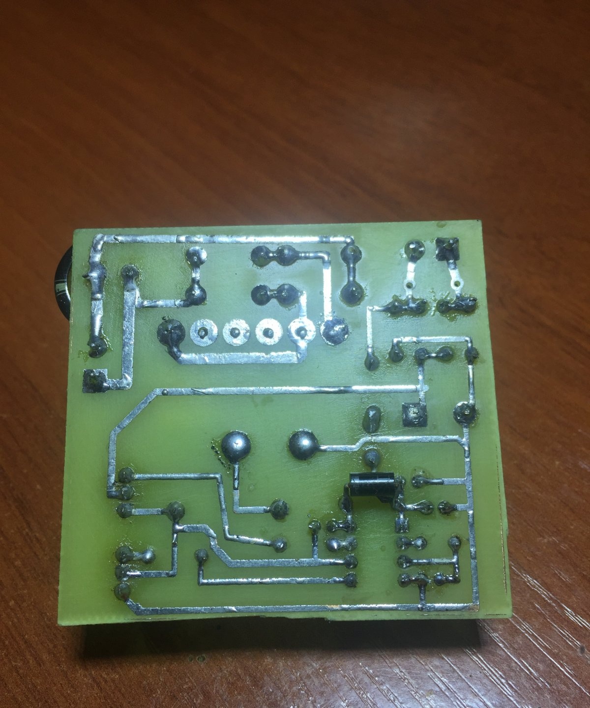
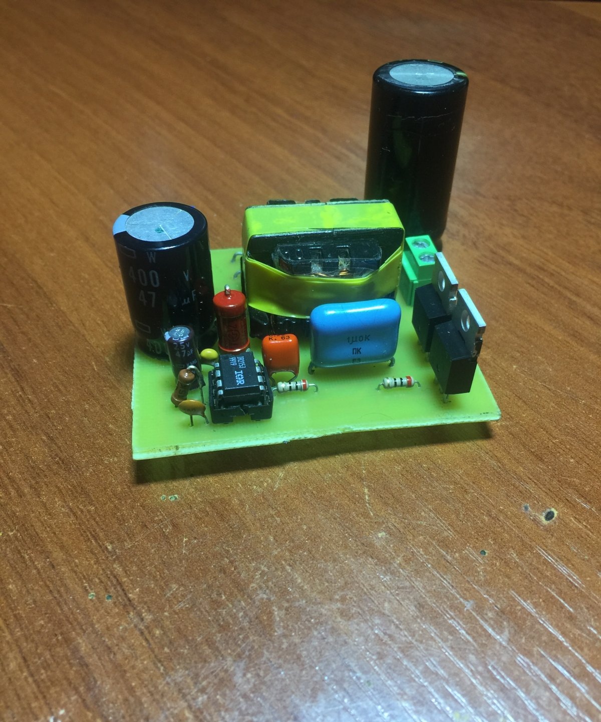
The printed circuit board is made on a piece of foil-coated single-sided fiberglass laminate using the LUT method. For ease of connecting power and connecting output voltage, the board has screw terminal blocks.
12 V switching power supply circuit
The advantage of this circuit is that this circuit is very popular of its kind and is repeated by many radio amateurs as their first switching power supply and efficiency and times more, not to mention size. The circuit is powered from a mains voltage of 220 volts; at the input there is a filter which consists of a choke and two film capacitors designed for a voltage of at least 250 - 300 volts with a capacity of 0.1 to 0.33 μF; they can be taken from a computer power supply.
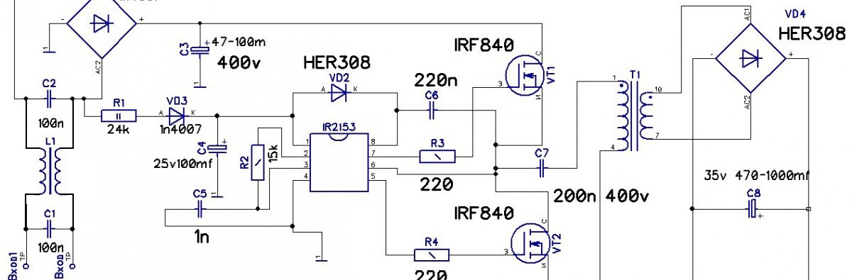
In my case there is no filter, but it is advisable to install it. Next, the voltage is supplied to a diode bridge designed for a reverse voltage of at least 400 Volts and a current of at least 1 Ampere. You can also supply a ready-made diode assembly. Next in the circuit there is a smoothing capacitor with an operating voltage of 400 V, since the amplitude value of the mains voltage is around 300 V.The capacitance of this capacitor is selected as follows, 1 μF per 1 Watt of power, since I am not going to pump large currents out of this block, in my case there is a 47 μF capacitor, although hundreds of watts can be pumped out of such a circuit. The power supply for the microcircuit is taken from the alternating voltage, here a power source is arranged, resistor R1, which provides current damping, it is advisable to set it to a more powerful one of at least two watts since it is heated, then the voltage is rectified by just one diode and goes to a smoothing capacitor and then to the microcircuit. Pin 1 of the microcircuit is plus power and pin 4 is minus power.
You can assemble a separate power source for it and supply it with 15 V according to the polarity. In our case, the microcircuit operates at a frequency of 47 - 48 kHz. For this frequency, an RC circuit is organized consisting of a 15 kohm resistor R2 and a 1 nF film or ceramic capacitor. With this arrangement of parts, the microcircuit will work correctly and produce rectangular pulses at its outputs, which are supplied to the gates of powerful field switches through resistors R3 R4, their ratings can deviate from 10 to 40 Ohms. Transistors must be installed N channel, in my case they are IRF840 with a drain-source operating voltage of 500 V and a maximum drain current at a temperature of 25 degrees of 8 A and a maximum power dissipation of 125 Watts. Next in the circuit there is a pulse transformer, after it there is a full-fledged rectifier made of four diodes of the HER308 brand, ordinary diodes will not work here since they will not be able to operate at high frequencies, so we install ultra-fast diodes and after the bridge the voltage is already supplied to the output capacitor 35 Volt 1000 μF , it is possible and 470 uF, especially large capacitances in switching power supplies are not required.
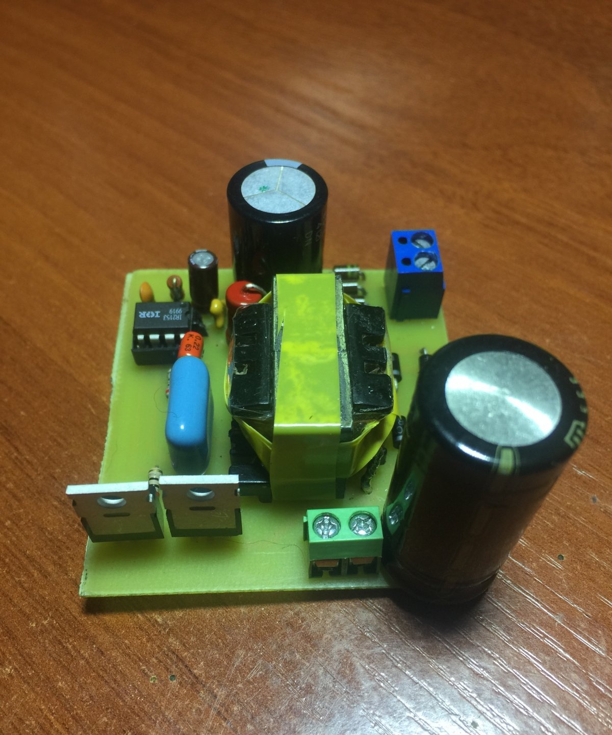
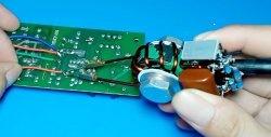
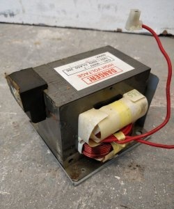
Let's return to the transformer, it can be found on the boards of computer power supplies, it is not difficult to identify it; in the photo you can see the largest one, and that is what we need. To rewind such a transformer, you need to loosen the glue that glues the halves of the ferrite together; to do this, take a soldering iron or a soldering iron and slowly warm up the transformer, you can put it in boiling water for a few minutes and carefully separate the halves of the core. We wind up all the basic windings, and we will wind our own. Based on the fact that I need to get a voltage of around 12-14 Volts at the output, the primary winding of the transformer contains 47 turns of 0.6 mm wire in two cores, we make insulation between the windings with ordinary tape, the secondary winding contains 4 turns of the same wire in 7 cores . It is IMPORTANT to wind in one direction, insulate each layer with tape, marking the beginning and end of the windings, otherwise nothing will work, and if it does, then the unit will not be able to deliver all the power.
Block check
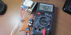
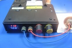
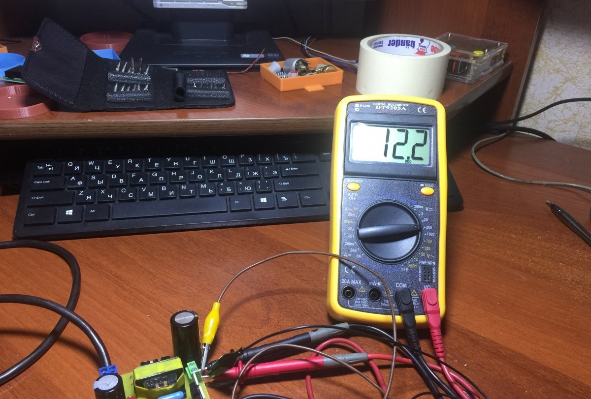
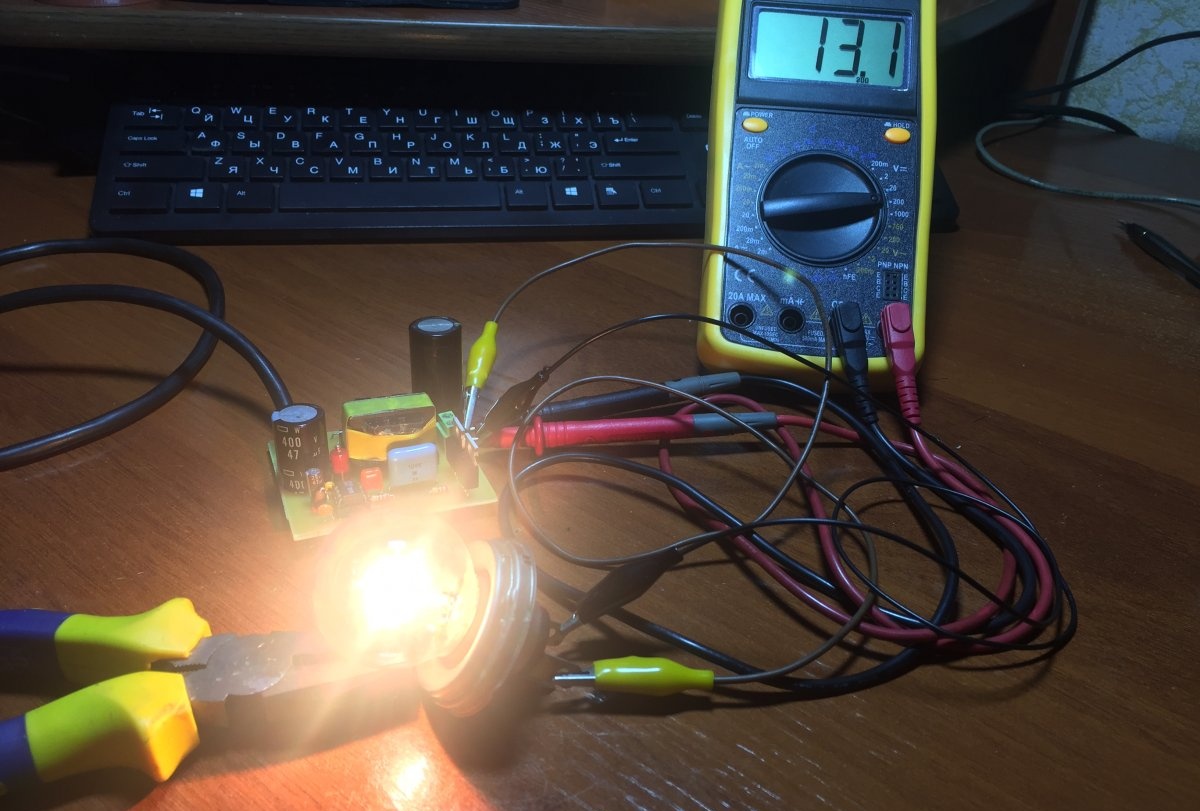
Well, now let's test our power supply, since my version is completely working, I immediately connect it to the network without a safety lamp.
Let's check the output voltage as we see it is around 12 - 13 V and does not fluctuate much due to voltage drops in the network.
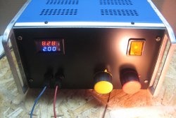
As a load, a 12 V car lamp with a power of 50 Watts flows a current of 4 A. If such a unit is supplemented with current and voltage regulation, and an input electrolyte of a larger capacity is supplied, then you can safely assemble a car charger and a laboratory power supply.
Before starting the power supply, you need to check the entire installation and connect it to the network through a 100-watt incandescent safety lamp; if the lamp burns at full intensity, then look for errors when installing the snot; the flux has not been washed off or some component is faulty, etc. When assembled correctly, the lamp should be slightly flash and go out, this tells us that the input capacitor is charged and there are no errors in the installation. Therefore, before installing components on the board, they must be checked, even if they are new. Another important point after startup is that the voltage on the microcircuit between pins 1 and 4 must be at least 15 V. If this is not the case, you need to select the value of resistor R2.