Miniature devices for taking exams
CONTENT
Small-sized transceiver for exams
Making a miniature earphone with your own hands
Wireless earphone for exams-1
Wireless earphone for exams-2
Wireless micro-earphone on a chip
Wireless hidden earpiece
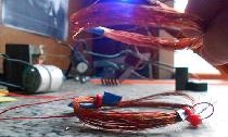
This transceiver is one of my first developments. I don’t remember whether before or after the movie “Operation Y”, I assembled a portable transceiver and with its help I successfully passed only one exam - “Scientific Communism”. All other exams did not cause problems.... And my fellow student Zilberstein dictated to me from notes ( maybe he will respond?).
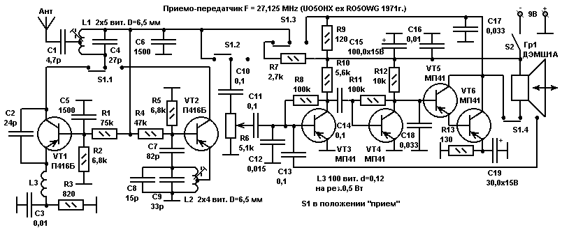
Powered by a Krona battery. Volume control R6 with a switch from a pocket receiver. The range, several tens of meters, covered the entire Institute of Communications (OEIS). An antenna made of flexible wire 1-1.5 meters was placed under the jacket on the back. DEMSH1A capsule is connected cable in the screen, passed into the sleeve and placed under the watch bracelet.Transferring it to his fist, he whispered the topic of the ticket, and propping his ear up, he barely had time to write it down. The S1 switch, a French prototype of the P2K, was activated by pressing the elbow on the trouser pocket.
So the session came and “damn”, i.e. the teacher with a bucket of nails is trying to hammer them into your ass. No, I will not suggest an original nail puller design. Let's talk about how to avoid the most unpleasant process of hammering “nails” using modern technologies. I came up with this back in 1996, when I was in my first year at university. Well, actually, I studied for 5 years and came out as a specialist with a clear conscience and an empty head :-). Palev was never there. This was the preamble, so to speak.
So we need:
1. superglue
2. a powerful magnet from a computer hard drive.
3. used AA battery.
4. Relay RES-10 in a disassembled state from which we need a thin wire. Other relays will also work. The main thing is a thin wire. The thinner the better.
5. Foil-coated fiberglass.
6. dead Chinese earphone. All it needs is a membrane.
7. a used pen refill with a diameter of 2.5 - 3 mm and two washers that would fit on it and not come off.
Technology
We take the AA battery and remove the tin jacket from it. From this tin we cut out a strip 22-25 mm long and 3-4 mm wide. Then we bend it so that we get a cylinder. We solder the seam of the cylinder. This is the base of the earphone.
Now you can start making the base. To do this, take fiberglass with a thickness of about 0.3-0.5 mm (if necessary, it delaminates well) and a circle of the required diameter is cut out of it; it must fit into the body with force.Alternatively, you can etch the entire design in advance and then cut everything out with scissors. You can also cut through all the contact pads with a cutter knife. Along the edge of the circle, fiberglass laminate is soldered to the base of the cylinder. At this point the body is ready.
Now you need to glue the magnet to the base. A simple magnet will not work here; you need a very powerful one and it is obtained from fallen hard drives. One magnet from there is enough for a lot of headphones. The magnet obtained from the most sacred place of the computer crumbles!!! with pliers into cubes sized according to the scale (2x2x2 mm) of the given drawings. One of the resulting cubes (cubes are obtained for the first time after about 10-20 minutes of crumbling) is glued!!!!!!attention!!!!!! southern!!!! or !!!!! north!!! pole to the base. You can determine which pole is which with the help of some magnet from a broken Chinese earphone. Glued with superglue. The main thing is not to cover the two holes on the base.
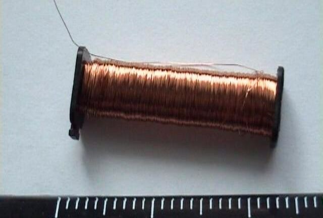
The membrane is obtained from Chinese headphones (and the more Chinese the earphone, the better because the membrane is thinner “it seems to me that they even save polyethylene” since the excessive rigidity of the membrane affects the volume of the headphone). The wire for the coil is obtained from a RES-10 type relay. The reel is wound on the shaft of a fountain pen D = 2.5mm, so that the winding does not spread out, stop washers are put on the shaft. A hole is made in the rod into which one end of the wire is inserted. Before you start winding for the first time, you should practice and wind several test coils; they should not be very large because may later cling to the magnet. The coil resistance should be in the range of 20-80 Ohms, which is approximately 80 or more turns.When winding, the wire is slightly moistened with “moment” or BF, you can also use superglue, but carefully so that the coil does not fall apart later when you remove it. Immediately after winding, it is removed so that it does not dry out, but if it does dry out and stick, you can use alcohol, which quickly dissolves the moment. After several unsuccessful attempts to remove the coil from the frame without damaging it, it must be glued to the membrane!!!!!!!!!!! using a minimum of superglue. Under no circumstances should you apply superglue to the membrane in places where it does not come into contact with the coil - otherwise the membrane will become rigid and the earphone will work quietly. Tin the coil wires at a distance of 2 mm from it.
Now, having inserted the coil wires into the holes in the base, the membrane is glued with a minimum of superglue to the outside of the body - the cylinder. The wires are soldered to the contact pads. In this case, you must try in every possible way not to overheat the earphone, otherwise the magnet or something else may fall off. Now test with an ohmmeter and make sure everything is ok 20-80 ohms.
Wireless earphone for exams
(Option 1)
This device was assembled not out of necessity, but because its circuit diagram was not available on the network.
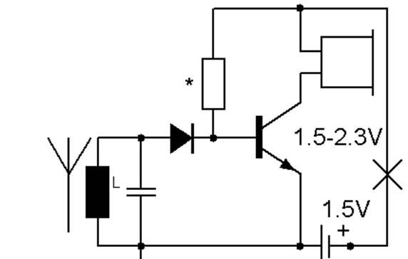

The receiver of the device is simple: it is a detector receiver with one amplification stage.The input circuit is made up of a resistor and a capacitor; the voltage induced in the circuit is detected by a diode and is then amplified by a transistor in the collector of which a high-impedance earphone is installed; it acts as a load; a small base bias is achieved by a resistor whose resistance mainly depends on the amplification factor of the base current; its resistance can be within 200 -430kOhm. This simple circuit design provides high parameters with very small dimensions. The transistor used was the domestic KT3130; when choosing a transistor, one should strive for its maximum amplification. The diode was a silicon diode with a Schottky barrier type KD514 or a similar imported one! Of course, it would have been better to use germanium, but miniature ones could not be found. Resistor RC0402 5% from 200 to 430 ohms (select when tuning to the maximum undistorted signal. In the receiver circuit, any SMD choke is suitable, I used 1 μH type SDR0402 type/size 0402 from Bourns. SMD capacitor type GRM size 0402 +/- 5% TKE MP0 with a capacity of 39 picoforads, which in the circuit corresponds to approximately 25 MHz. Earphone type TEM-1957, TEM-1956, TEM-1958M, TEM-1958, TEM 2632 or any miniature, the main thing is that its resistance is at least 300 Ohms, better yet even higher. Battery, it should choose the smallest possible electronic wristwatch. But you should not forget that the smaller it is and the cheaper you buy it, the less it will last! It may not last until the end of the exam. Due to the lack of miniature headphones, I cannot lay out the design of the entire headphone, although it’s not difficult to guess, they should appear soon, then the article will be much more complete and inexpensive kits for self-assembly will appear!
Transmitter.
The circuit is quite simple - it's just an AM modulated transmitter tuned to a frequency of 25 MHz. It consists of an audio frequency amplifier, modulator and the high frequency generator itself.
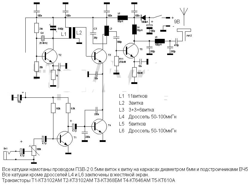
The base of transistor T4 must be supplied with a bias voltage through a resistor; it is missing in the circuit. 180 kOhm resistor from the power supply positive to the base of transistor T4
The ULF (T 1) and modulator (T 3) do not need adjustment. The master oscillator is adjusted by changing the position of the common coil trimmer L 1, L 2 and changing the values of capacitors C 6 to the maximum of the wave meter. The next stage is L 3. It may be necessary to select the values of the base resistor 24 kΩ (the current of the master oscillator transistor). When tuning the antenna by changing the P-filter capacitors and adjusting L 5, it is advisable to use a wave meter. When setting up the output stage and matching it with the antenna, it is advisable to take into account the non-optimal length of the antenna, which reduces the radiated power of the transmitter. Therefore, it is advisable (as in the previous case) to use additional inductance (although this is not mandatory), increasing the effective length of the transmitter's transmitting antenna. This coil is connected in series with the antenna (not shown in the diagram). The parameters of the elements of the U-shaped filter (L 5) and the additional coil coincide with the parameters of the previous design.
Here is another update, the scheme is working, but has not been used in practice yet.
Wireless earphone for exams
(Option 2)
This radio earphone differs from Option 1 even in its operating principle. It works using the inductive method. The coil that you will have on your neck is the primary winding, and on the earphone it is the secondary winding.All other electronics are low-frequency amplifiers. Now for the design.
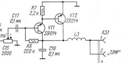
We wind a receiving coil onto the TEM-1958 earphone; it contains 70-100 turns of enameled wire of the PEV-2 type 0.05-0.07; a thicker one should not be used (it may not fit into the ear). The radio parts used in the radio earpiece can be seen in Fig. 1
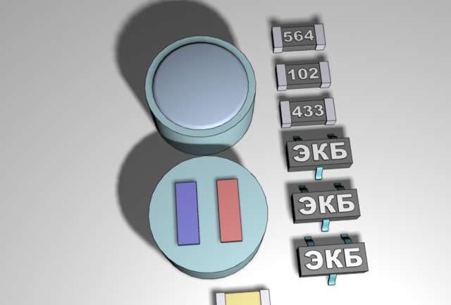
Rice. 1
All parts of the headphone can be mounted in two ways; the first, the simplest, is wall-mounted mounting, see fig. 2 and 3
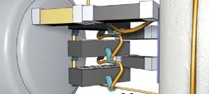
Rice. 2
Rice. 3
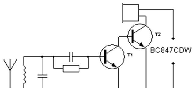
Now let's look at the headphone circuit. It is assembled quite primitively and does not require any adjustment if it is assembled from previously serviceable components. See Fig. for diagram. 4.
Rice. 4
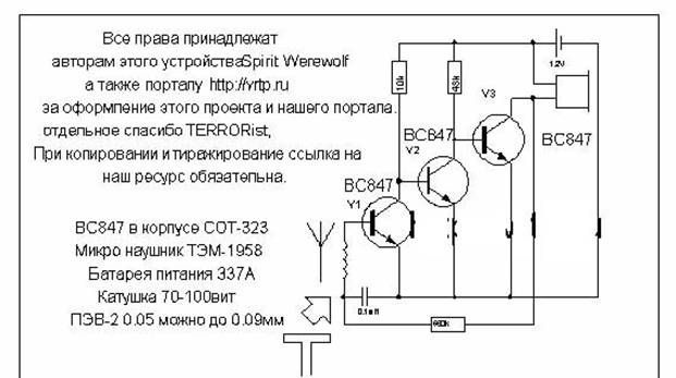
As can be seen from the diagram, this is a conventional low-frequency amplifier with direct coupling(s); the coil is connected through an isolation capacitor. All transistors in our version were chosen as enemy ones, mainly because of the miniature package of the SOT-323 type; they are called BC847. You can use any other low-power sound, even the structure does not matter, only the standard size. (In case of changing the transistor structure, simply change the polarity of the device's power supply.)
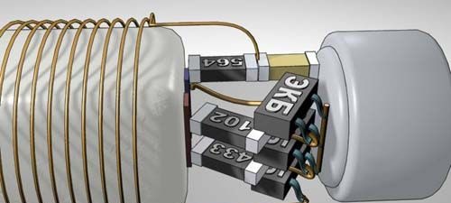
Transmitter antenna (see Fig. 5)
It is simple to make. The wire is 0.33mm or so in diameter. It is better to take a flexible mounting one, the softer it is, the better. You also need heat shrink tubing that is close to the color of the clothing or body. But this does not necessarily mean just faded tones. On a mandrel (can pan or something) 20 cm in diameter, measure out the heat-shrinkable tube by bending it and cut it off. We do the same, I thread a rocky wire about 1-2 mm thick into a thermal tube and tie our wire to one end using any convenient method. This will be a makeshift needle.Now we measure out a piece of wire, measuring its resistance; it should be about 16 nm. Now we begin to thread the wire around the gap between the ends of the tube. When everything is ready, you will have a ring with a diameter of 20 cm with at least 40 turns of wire. We shrink the tube with warm air and clean the two ends by soldering to them a piece of shielded wire from faulty headphones for the player, it’s good if the connector on the wire is useful later, since you don’t have to assemble the amplifier, but connect the antenna to the player, receiver, etc. At the joint (soldering) we put a piece of tube 5-8 cm in length, taking into account that the tube covers the solder and the antenna coil folded in two enters it. The transmitter of this antenna can be any audio power amplifier more than 50 mW and capable of operating at a load of 8-16 ohms.
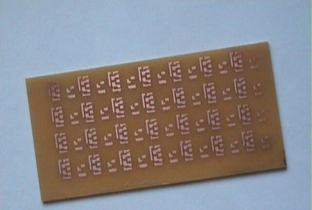
Printed circuit board of the second layout option.

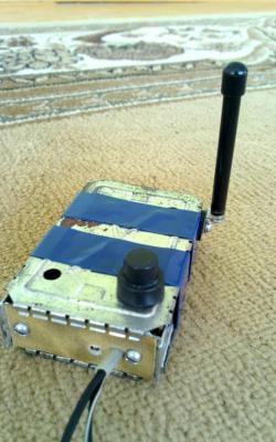
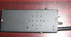
The article has not yet been written to the end and people are already confused about it. They probably pass their exams with flying colors. Dmitry sent photos of his device (see below).
Amplifier (option No. 1)
Transmitter amplifier No. 2. It couldn't be simpler. The difference is that you will have to wind the coil to the resistance indicated in the diagram. (instead of speaker)
Amplifier circuit
Wireless earphone for exams
(Option 2 - continued)
How to make an amplifier (transmitter):
1). We buy an ordinary Chinese radio with automatic tuning, without a speaker. Any model will do since the circuit is practically no different.
2). Let's disassemble the radio.
A). We find the microcircuit. Carefully remove legs 2, 4, 5. (If you look at the chip from above, and assume that the first leg is next to the mark).
b). We find the headphone jack. We find the socket leg, which sends a signal to the middle contact of the plug (if the plug is stereo).We find the path that goes from this leg and cut it off. In general, the socket will be adapted for a mono plug. An antenna worn around the neck will be stuck there.
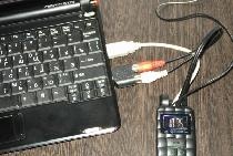
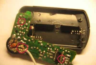
V). We find a variable resistor, which is a volume control and a switch. Its two outer contacts go to the hundsfree instead of the earpiece (see photo_1).
3). We cut a place in the radio housing for the hundsfree wire. We close everything as it was in the housing. The amplifier is ready for use! (see photo_1)
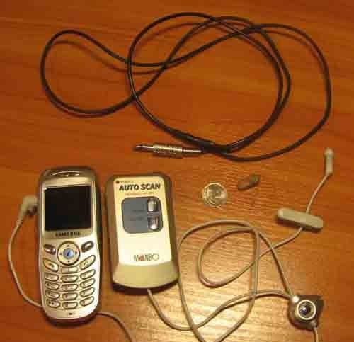
Photo 1
We connect the phone to hundsfree (hundsfree must match the phone!). Instead of headphones, we plug an antenna into the amplifier (former receiver).
Hundsfree:
Hundsfree doesn't need any special modifications! Instead of a headphone, we connect an amplifier. You can open the hundsfree button and pull out the microphone from there. Make it on a separate wire (see photo_1). The most important thing: hundsfree must be selected for a specific phone model. Otherwise, there may be problems with sound.
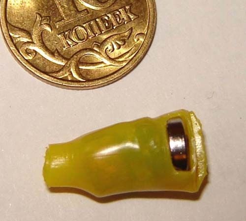
Micro earphone.
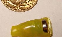
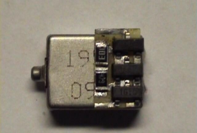
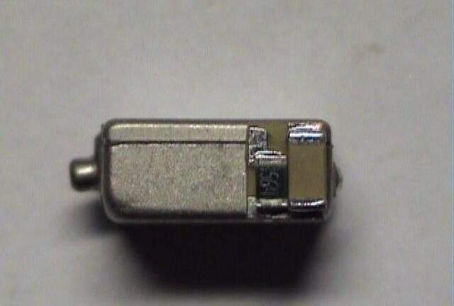
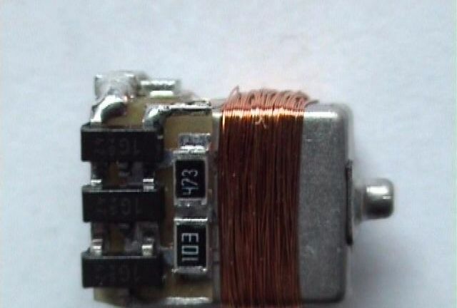
The headphone coil is wound directly on the telephone capsule (TEM) along it! After winding, it is convenient to fix the turns on the capsule using super glue. The earphone parts are mounted on a board, which simplifies the assembly process and allows you to solder chip parts of size 0805 and smaller. The battery location is located at the back of the earphone. The board is located above the battery. The headphones turn out to be a little thicker at one end, which holds it well in the ear and prevents it from getting into the brain! :0)
The contacts for the battery are cut from a copper screen (from some kind of coil) and soldered to the board. The capsule with a coil wound on it can also be glued with super glue to one of the battery contacts (through a gasket). The entire system is driven into a heat-shrinkable tube with a diameter of 9-10 mm.and using a hair dryer or an ordinary candle, it is carefully brought into a ready-made state (in this case, the battery must be inserted into the earphone, and the tube on the wide side of the earphone should be clamped with tweezers; after cooling, a beautiful seam will form in the clamped area, which can be trimmed with wire cutters). See photo.
I wanted to add it especially for crazy hands! In order not to buy or break the receiver, even if it is Chinese, let's turn to its circuit diagram. see below
From it we see that most of it is not used, but only an AF amplifier assembled on two transistors is used! We can replace them with domestic ones, for example, KT3102. It won't be worse, maybe even better. This amplifier is capable of delivering power with distortion, which will be enough for high-quality operation of the headphone. But there are also pitfalls: this circuit will not give high-quality sound and it will be at the level of industrial designs! But we are radio amateurs and will not stop there.
A higher quality AF amplifier can be assembled using one cheap microcircuit and four discrete elements. I hope there is no need to explain what we will turn on instead of headphones? Yes, that’s right, the transmitter coil hanging limply from his neck.
Now we have come to the final part of the article. And let's put an end to this.
Wireless earphone for exams
(Option 2 - ending)
Manufacturing option.
We assemble the radio earpiece, the assembly of which will be discussed, according to the diagram (Fig. 1), which was already presented earlier. To do this, we will need all the radio components (SMD) shown in the diagram, a TEM-1958 electromagnetic telephone, a heat-shrinkable tube (preferably flesh-colored) and an enameled wire 0.04-0.05 mm (you can get it by breaking a Chinese alarm clock).
Rice. 1
First of all, we make a printed circuit diagram on a computer, since it is already ready, we just download, print and make the board directly.
Rice. 2
Rice. 3
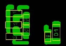
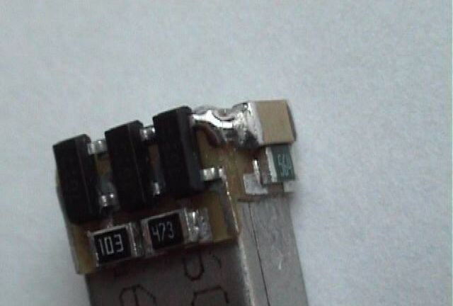
The printed circuit diagram, as can be seen in the figure, consists of two separate parts. On the main board there are: transistors V1-V3 and resistors 10K and 43K. The second board contains: a 0.1mF capacitor and a 560K resistor.
Rice. 4
Rice. 5
Rice. 6
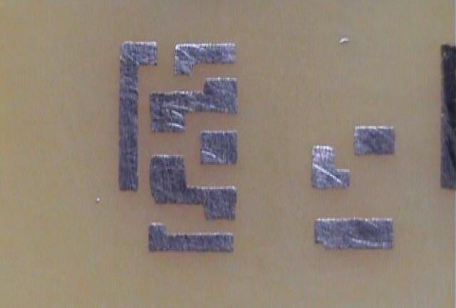
Because the radio earphone must be as compact as possible, therefore the board must also be manufactured with the utmost care. In order for the boards cut in this way to be not only small in area (Fig. 6), but also in thickness, we begin to very carefully and painstakingly sand the surface of the board from the back side, and at the same time the nails. To begin with, it is best to use coarse sandpaper, and only then, when the back surface is sanded to a minimum (the main thing here is not to overdo it!) We take, if possible, fine sandpaper and carefully refine the surface, remembering that with this surface both boards will be glued to the TEM body -1958.
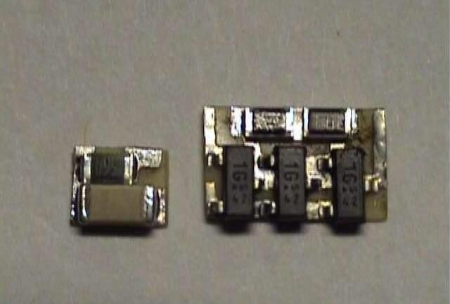
Next, as expected, is the soldering of the elements. It is best to solder on some kind of metal surface that will absorb excess heat, because when soldering onto such a thin board, traces may come off! (well, it all depends on your ability to solder). We glue the finished boards with reliable superglue so that the boards are connected to each other (Fig. 9), solder the joint (exactly the place where the capacitor connects to the emitters of the transistors). We remove the protruding edges with a scalpel!
Rice. 7
Rice. 8
Rice. 9
Now we take the coil (Fig. 10) with the previously mentioned enameled conductor and wind 70-100 turns onto the remaining free space on the TEM-1958 and, according to the diagram, solder its ends to the boards.For reliability, you can drop a little glue onto the reel. Using a conductor with a large diameter can lead to self-excitation of the earphone (high-frequency squeak).
Rice. 10
Rice. eleven
If the workpiece looks like this then you are in the right direction!
To make a battery housing we use tin (can be removed from an old battery) and material for making circuit boards. From a tin we cut out the main part of the fasung body (which is also the “+” terminal), see Fig. 12, from the material for making circuit boards we cut out a circle with a diameter of 6 mm and again take sandpaper and grind the surface and already bleeding fingers to a minimum, This is what we got as the “-” terminal. As a result, the fassung looks like this, see. Fig. 13.
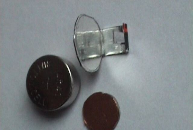
Rice. 12
Rice. 13
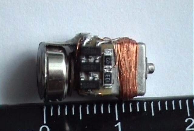
Now the very important moment has come: “Installing the fasung”. If you don’t concentrate now, then consider it a failure! First of all, we solder the “+” terminal to one of the TEM-1958 contacts (preferably to the right one, if you look from the side of the markings and taking into account that the contacts are on top). This must be done very carefully and quickly, because these contacts fall off very quickly and then that’s it , "haemorrhoids"! Well, if everything worked out, then you can continue further, so that this glue does not fall off in the future and spoil your mood, then it needs to be properly glued or filled with two-component superglue (its durability is 250 kg/cm?, maybe weaker), at the same time glue the “-” terminal (But before that, do not forget to connect the second contact of the TEM to the circuit, otherwise it will be too late!) The “+” terminal should not contact the body!
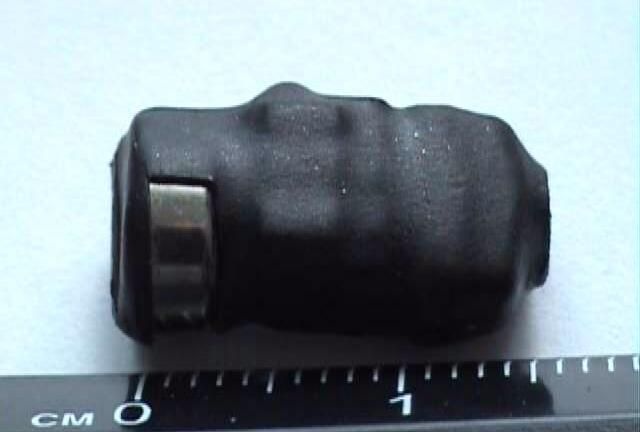
After the glue has dried well, we add, according to the diagram, the missing connections; for this we use an enameled conductor. In the places where it will pass, we spill a moderate amount of Chinese second glue so that it does not shorten (insulation). At the end, we place the resulting structure in a heat-shrinkable tube (the battery must be in the container!), heat it with a hair dryer or lighter, clamp the heated tube from the battery side with tweezers, and carefully remove the protruding limbs with a scalpel. A correctly assembled earphone will emit a slight hiss!
Rice. 14
Rice. 15
Rice. 16
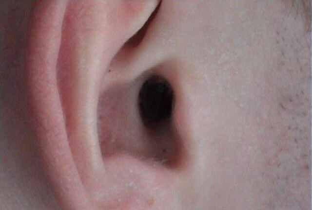
This is how it looks in the ear!
The manufacture of the transmitter antenna is described in previous articles!
Wireless micro-earphone on a chip
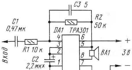
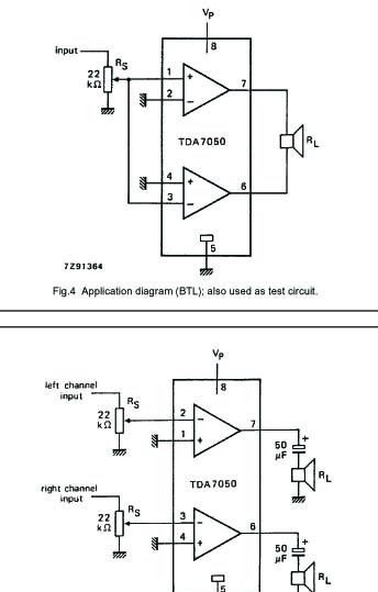
For today's exam, I assembled this entire setup on the TDA7050 chip, both the loop amplifier and the earphone itself.
For the loop I used a microcircuit in a regular package. The connection circuit is similar to a stereo (lower), only I connected the 2nd and 3rd legs together, and the 7th and 8th go separately to capacitors. But after them, not with 2 speakers, but connected together and in a loop (purely by ear, the sound is more powerful than using the mono version, i.e. the top 1st circuit), the second end of the loop is naturally on the minus side.
The loop was wound at 32 ohms. As a battery I took a battery from a Samsung X100.
If possible, it is better to assemble an amplifier for the loop using m/s TDA7052, the earphone picks up much better!
In the earphone itself I used a microcircuit in an SMD case. The speaker was taken from Nokia (the one that seems to be 60 Ohms). I assembled it according to the first scheme, but only without any resistors and capacitors, i.e. I connected a coil to the input (without capacitors and resistors!!!), which I wound around the microcircuit.
And so that there was more resistance, I simply wound more turns (I wound it manually for 12-13 minutes with a 0.01 mm wire until the wire itself broke, and attached it to the minus at this point).
I used two LR41 batteries (they were a little small, but they fit). And it was a good learning experience, for me the best option, because... They don’t sell small parts in my city at all, I didn’t immediately find the microcircuit. The size of the “ear” is, in principle, normal, but let’s say it might not fit with my classmate.
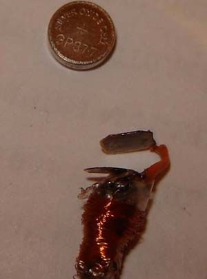
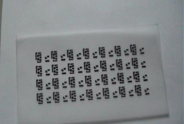
Here are the pictures, although these are draft versions (the body is made of paper to at least somehow hold the batteries), because I haven’t found a heat shrink tube of the required diameter yet.
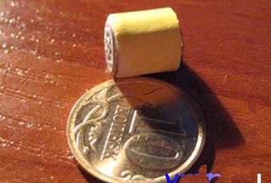
Well, what’s under the piece of paper, of course, needs to be done more closely
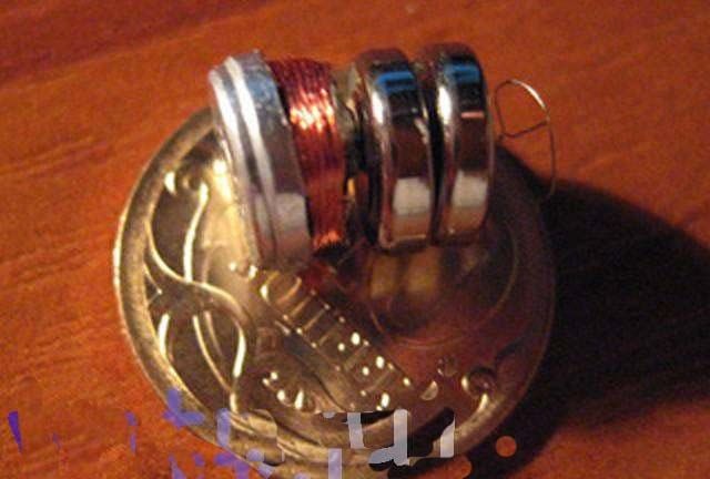
Perhaps the most important part: the coil is wound directly onto the microcircuit attached to the speaker. Everything was soldered with a 45-watt soldering iron, because... There is nothing particularly complicated and there are no small parts either: only a microcircuit and a speaker from Nokia, and of course a coil.
Of course, if you do everything more carefully and put smaller batteries, then you can still win in length 1-1.5 mm and in diameter in the area of the batteries. Only the diameter of the speaker cannot be changed in any way, unless you find a smaller speaker. My version is 9 mm long including batteries. The diameter in the area of the speaker itself is 8 mm, where the batteries are up to 8 mm (depending on what batteries you put in).
I also used 361A batteries, they are the same in diameter as LR41 but thinner. 361A lasts for approximately at least 1.5 hours, I can’t say for sure, I checked it with old batteries. The current strength between them and the ear is approximately 5-6 mA (this is measured with a cheap old Chinese tester). But according to the manual for the microcircuit it is written that at 3V the current consumption is 3.2 mA.
As for noise, speech and music in the earphone are audible and quite understandable, but the fewer turns, the less audible, but also the less hissing. The more turns, the better you can hear both speech and hissing, although there is a certain limit, above which speech begins to disappear and hissing and sensitivity to all kinds of devices increases even more. You can, by leaning your ear against the wall, determine where the wiring goes without any problems.
Good luck everyone!!!!
P.S.. All information provided is used for self-education!!!! The site administration, as well as the author of the article, does not bear any responsibility for the incorrect use of information and any negative consequences.
Advice: If anyone has suffered from acute inflammation of the inner ear, which manifests itself in the fact that at some point the pus accumulated in the ear canal breaks through the eardrum and comes out, then it is better not to use this ear!!!!!!!!!
The eardrum is healing, but it is not completely retracted, leaving a small hole. Also, after this, hearing may be weakened by 10-15% (the timbre color changes, high frequencies are heard less well).