Do it yourself
Life hacks, master classes, useful tips, recipes.
home » Electronics » Simple circuits » Simple walkie-talkie with three transistors
This circuit of a shortwave radio station contains only three transistors. The simplest walkie talkie for beginner radio amateurs. The design was taken from an old magazine, but it has not lost a bit of its relevance. The only thing that is outdated is the radio components, which need to be replaced with modern analogues, as a result the characteristics of the radio intercom will improve.

Radio station diagram


A simple walkie-talkie with three transistors

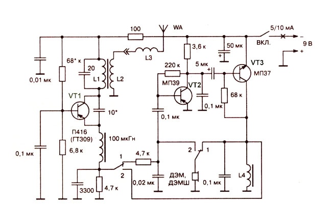
The scheme is simple, especially if you understand its operation. I suggest you immediately visually divide it into the left side with one transistor and the right side with two transistors. The transistor VT1 assembles a transmitter and a receiver at the same time. When the switch closes contacts “1”, the radio is in receive mode and this transistor operates in supergenerative detector mode. And when the contacts close to mode “2”, this is transmission and the transistor works as a master oscillator. With this, I think it’s clear.A simple low-frequency amplifier is assembled on transistor VT2, VT3, which, depending on the position of the switch, either amplifies the signal from the microphone and transmits it to the transmitter, or amplifies the signal from the supergenerative detector and transmits it to the loudspeaker. By the way, the loudspeaker and microphone are one and the same element - a high-impedance DEM telephone capsule.
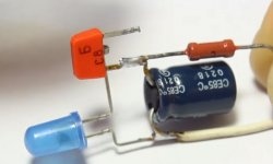
Radio parts


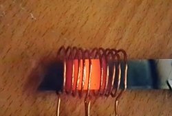
Coil L1 is wound on a frame with a diameter of 8 mm with a ferrite core turn to turn and has 9 turns of PEL wire with a diameter of 0.5 mm. Coil L2 is wound on top of coil L1 and has 3 turns of the same wire. Coil L3 has a diameter of 5 mm and contains 60 turns of PEL wire with a diameter of 0.5 mm. The primary winding of the output transformer of the transistor receiver can be used as inductor L4.

Antenna design


A simple walkie-talkie with three transistors

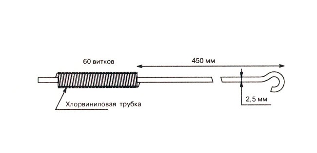
The antenna was made by me from thick aluminum wire, with a piece of insulation, on top of which the L3 coil was wound.
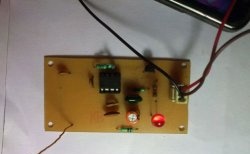
My modernization


I made such a walkie-talkie back in school, but then I already changed all the transistors to more modern ones with a high gain. For example, I replaced VT1, VT2 with KT361, and VT3 with KT315.
Now, of course, I would change the polarity of the power supply and the polarity of the capacitors, replace all the transistors from the n-p-n structure to p-n-p, and p-n-p to n-p-n. Well, I would install modern transistors. There are no particular requirements for transistors, so absolutely any will do.
The author of the diagram says that the range of action of radiums of the same type in open areas is 100-200 meters. I accelerated such radios to 500 meters, for this I used modern transistors, increased the antenna to 900 mm, plus increased the generator current by replacing the 100 Ohm resistor with a 50 Ohm one.Someone will say that it’s all due to the increase in the antenna, with which I disagree and will say that with the “native” antenna I was able to communicate over 300 meters.

Settings


If you assembled the radio correctly and from serviceable parts, then the entire setup will come down to setting the L1 coil to a frequency of 27 MHz. This can be done with a subline core or a capacitor in the circuit.
A simple walkie-talkie with three transistors

Lavrenko I. “Radio intercom” magazine “Radio Amateur”.
come back
Comment
  • bowtiesmilelaughingblushsmileyrelaxed relaxedsmirk
    heart_eyeskissing_heartkissing_closed_eyesflushedrelievedsatisfiedgrin
    winkstuck_out_tongue_winking_eyestuck_out_tongue_closed_eyesgrinningkissingstuck_out_tonguesleeping
    worriedfrowninganguishedopen_mouthgrimacingconfusedhushed
    expressionlessunamusedsweat_smilesweatdisappointed_relievedwearypassive
    disappointedconfoundedfearfulcold_sweatperseverecrysob
    joyastonishedscreamtired_faceangryragetriumph
    sleepyyummasksunglassesdizzy_faceimpsmiling_imp
    neutral_faceno_mouthinnocent
5+two=
Comments (11)
  1. Vania
    #1 Vania Guests 21 December 2017 13:19
    3
    L4 - it is quite possible to replace it with a 50-100 Ohm resistor, and it will work no worse.
  2. Nikita
    #2 Nikita Guests 10 March 2018 20:38
    4
    “Well, I would install modern transistors,” which ones would you recommend to install (taking into account changing the polarity of the condensers and power supply + replacing npn transistors with pnp, etc.) this is the first time I’m working on RF equipment, and also regarding SCR cores, will cores from tube TV boards be suitable? ?
  3. Nikita
    #3 Nikita Guests 10 March 2018 20:43
    2
    And can you tell us a little more about the antenna? As I understand it, you just need to take a piece of wire from the TV antenna and wind L3 around it, right? Apparently not, this is my first time working on RF technology, don’t swear too much)
  4. Anatoly Mukhin
    #4 Anatoly Mukhin Guests 2 April 2018 16:08
    2
    Quarter wave antenna, KT368, KT3102, KT3107, change the polarity of the power supply and electrolyte to 50 uF. and 315 and KT361 can’t even be called transistors, they’re just garbage, I always threw them out of all devices and replaced them with 3102 and 3107, the same can be done in the first two stages with 3107, but it’s better in the first P609 and in the third 3102 and leave everything unchanged.
    1. Guest Sergey
      #5 Guest Sergey Guests 11 September 2018 16:08
      3
      Cool. Who will set the transistor modes? For silicon and germanium they are very different.
  5. Gleb
    #6 Gleb Guests 3 February 2019 12:14
    3
    Hi, is it possible to replace the SCR core with a ferrite one?
  6. Wik
    #7 Wik Guests 26 June 2019 20:15
    5
    L4 can be used for the entire trans, the secondary can be connected to the damsh.
  7. Stas
    #8 Stas Guests October 31, 2020 11:53
    1
    How to tune this radio to 27 MHz
  8. Guest Alexey
    #9 Guest Alexey Guests 8 December 2021 21:49
    2
    I’ve played too hard with these super-regenerative monsters. The frequency constantly jumps due to temperature changes, and from the tray to the head the capacitance of the circuit will also change and you can’t do anything about it. You’ll just fuss around, constantly adjusting the circuit, like a radio operator. With an antenna for this range, are you going to catch 30-50 cm of wires? Are you seriously? It is better to reconfigure the input circuit from a Chinese FM receiver to 144 MHz, stability and range will increase significantly. And throw out the amplifier on two transistors and replace it with an op-amp, the same lm. And in this miracle, what the hell 500 meters are we talking about, whose ear are you rubbing?
  9. Guest Dmitry
    #10 Guest Dmitry Guests 8 August 2022 16:37
    1
    I already shed a tear remembering this diagram; I assembled it in childhood, when there were no traces of cell phones. Yes, there was a time when the joy of what you had assembled and it worked was simply enormous.I placed the antenna on the roof of a 5-story building and a friend received me on a P250 at a distance of about 800-1000 m, but the frequency fluctuated, of course)
  10. Valera Pronin
    #11 Valera Pronin Guests 24 February 2023 12:41
    1
    Can 27 MHz quartz be inserted into the base and ground circuit of transistor VT1, while removing the 0.1 µF capacitor? I checked that it will work in transmission, but how does it work in reception? You can also infuse quartz at a frequency of 27 MHz. Having removed the capacitor between the base and ground (inserting 27 MHz quartz instead), take a field strength detector, connecting it to the oscillatory circuit, namely to the collector circuit of transistor VT1. The setting will come down to the fact that the voltmeter needle should deviate to the maximum there and the frequency will be 27 MHz. The antenna can also be configured by making it from the telescopic tube of a radio or television. In my case, the fully extended tube is 45cm.
    Taking a suitable frame with the diameter of a felt-tip pen, I wound + - 40 vit 0.7 mm (in my case), keep in mind that you will have to adjust the antenna yourself. The antenna at 27 MHz is very narrowband. (I adjusted it according to the maximum indicators of the detector)

Fried crucian carp pieces in a frying pan

Test of low temperature welding rods with Aliexpress

Art Deco mirror | Do it yourself

Mittens with voluminous flowers | Do it yourself

«Do it yourself - with your own hands» - a site of interesting homemade products made from scrap materials and items at home. Step-by-step master classes with photos and descriptions, technologies, life hacks - everything a real master or just a craftsman needs for needlework. Crafts of any complexity, a large selection of directions and ideas for creativity.

We recommend reading

Washing machine error codes