The simple circuit of an automobile PWM regulator offered by Jericho Uno is not a professional, fully debugged design, notable for its safety and reliability. This is just a small cheap experiment, assembled using available budget parts and completely satisfying the minimum requirements. Therefore, its developer does not take responsibility for anything that may happen to your equipment when operating the simulated circuit.
NE555 PWM regulator circuit

To create a PWM device you will need:
- electric soldering iron;
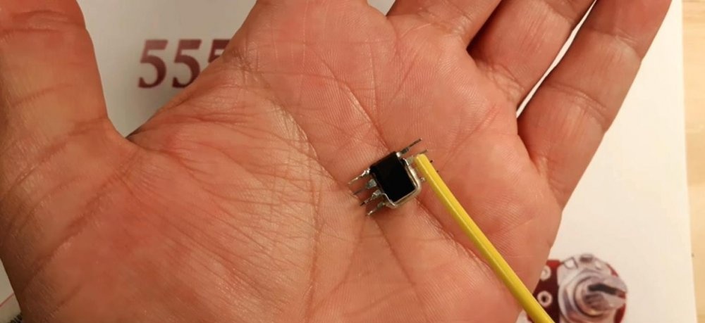
- chip NE555;
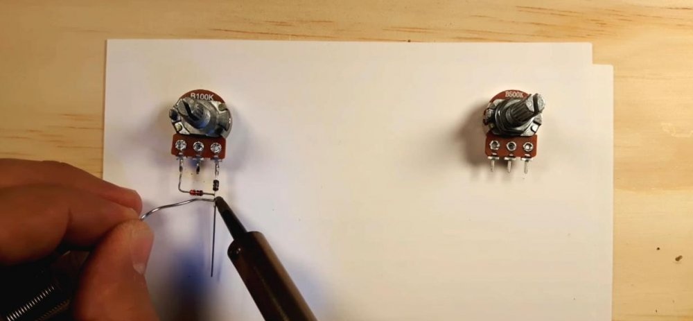
- variable resistor 100 kOhm;
- resistors 47 Ohm and 1 kOhm 0.5W each;
- 0.1 µF capacitor;
- two diodes 1N4148 (KD522B).
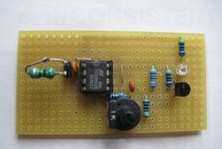
Step-by-step assembly of an analog circuit
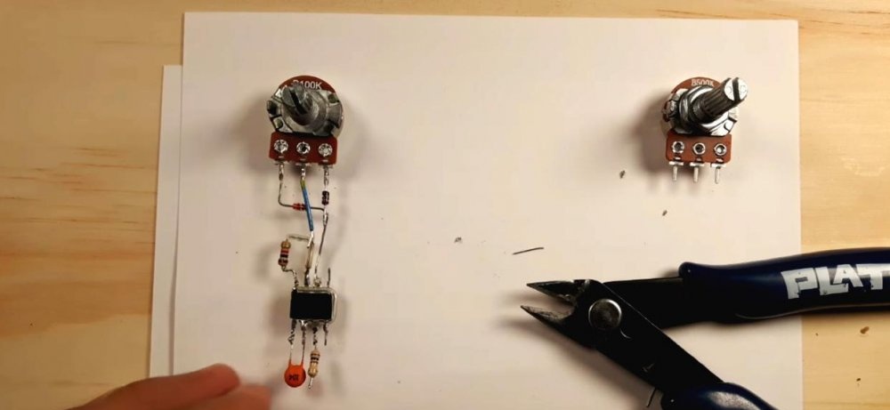
We begin building the circuit by installing jumpers on the microcircuit. Using a soldering iron, we close the following timer contacts with each other: 2 and 6, 4 and 8.
Next, guided by the direction of electron movement, we solder the “arms” of the diode bridge to a variable resistor (current flow in one direction). The diode ratings were selected from available, inexpensive ones. You can replace them with any others - this will have virtually no effect on the operation of the circuit.
To avoid short circuits and burnout of the microcircuit when the variable resistor is unscrewed to its extreme position, we set the power supply shunt resistance to 1 kOhm (pins 7-8).
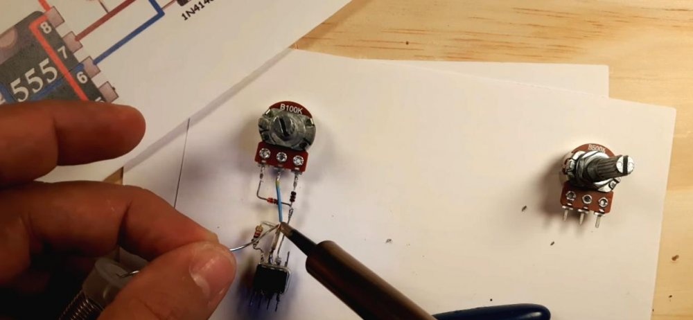
Since the NE555 acts as a saw generator, to obtain a circuit with a given frequency, pulse duration and pause, all that remains is to select a resistor and capacitor. An inaudible 18 kHz will be given to us by a 4.7 nF capacitor, but such a small capacitance value will cause a misalignment of the shoulders during operation of the microcircuit. We set the optimal value to 0.1 µF (contacts 1-2).
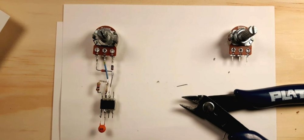
You can avoid the nasty “squeaking” of the circuit and pull the output to a high level using something low-impedance, for example a 47-51 Ohm resistor.
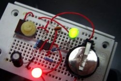
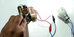
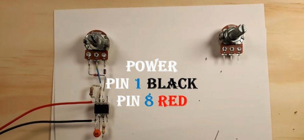
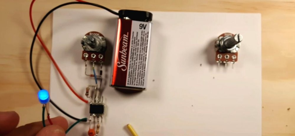
All that remains is to connect the power and load. The circuit is designed for the input voltage of the car's on-board network 12V DC, but for a visual demonstration it will also start from a 9V battery. We connect it to the input of the microcircuit, observing the polarity (plus on leg 8, minus on leg 1).
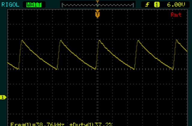
All that remains is to deal with the load. As can be seen from the graph, when the variable resistor lowered the output voltage to 6V, the saw at the output (legs 1-3) was preserved, that is, NE555 in this circuit is both a saw generator and a comparator at the same time.Your timer is operating in a-stable mode and has a duty cycle of less than 50%.
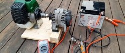
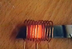
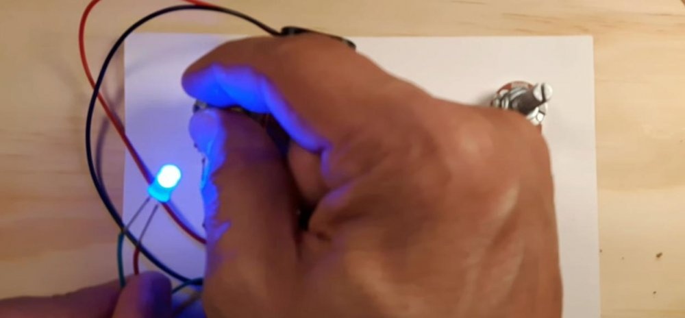
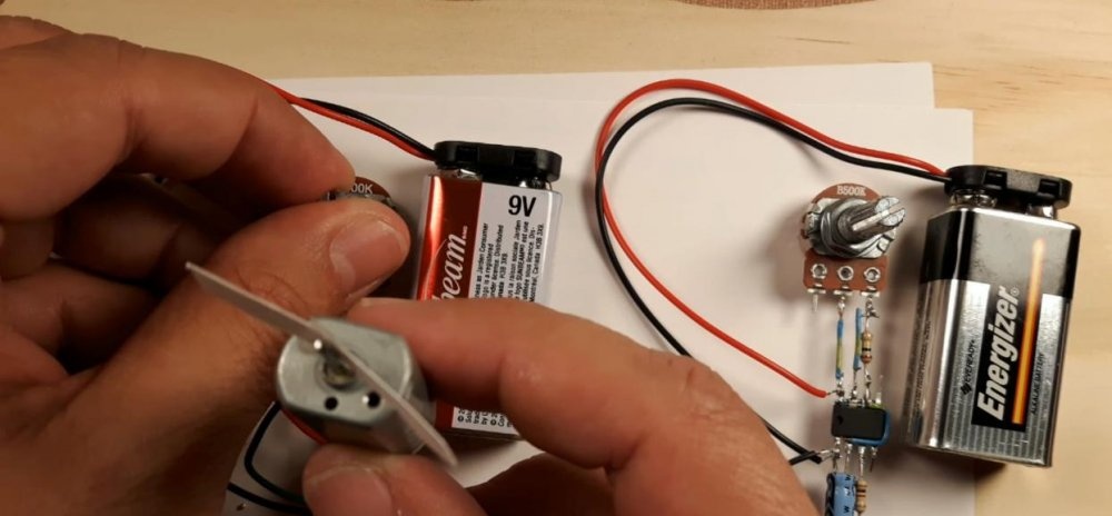
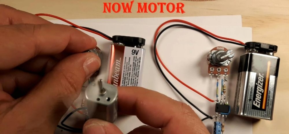
The module can withstand 6-9 A of direct current throughput, so with minimal losses you can connect to it both an LED strip in a car and a low-power engine, which will dispel smoke and blow on your face in the heat. Like that:
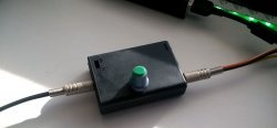
Or like this:
Operating principle of a PWM regulator
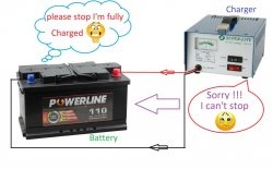
The operation of a PWM regulator is quite simple. The NE555 timer monitors the voltage across capacitance C. When it is charged to the maximum (full charge), the internal transistor opens and a logical zero appears at the output. Next, the capacitance is discharged, which leads to the closing of the transistor and the arrival of a logical one at the output. When the capacity is completely discharged, the system switches and everything repeats. At the moment of charging, the current flows along one side, and during discharge it flows in another direction. Using a variable resistor, we change the ratio of the shoulder resistance, automatically lowering or increasing the output voltage. There is a partial frequency deviation in the circuit, but it does not fall into the audible range.