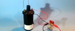
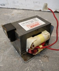
Nowadays, you can often find outdated CRT TVs in the trash; with the development of technology, they are no longer relevant, so now they are mostly getting rid of them. Perhaps everyone has seen on the back wall of such a TV an inscription in the spirit of “High voltage. Do not open". And it hangs there for a reason, because every TV with a picture tube has a very interesting little thing called TDKS. The abbreviation stands for “diode-cascade line transformer”; on a TV it serves, first of all, to generate high voltage to power the picture tube. At the output of such a transformer, you can get a constant voltage of as much as 15-20 kV. The alternating voltage from the high-voltage coil in such a transformer is increased and rectified using a built-in diode-capacitor multiplier.
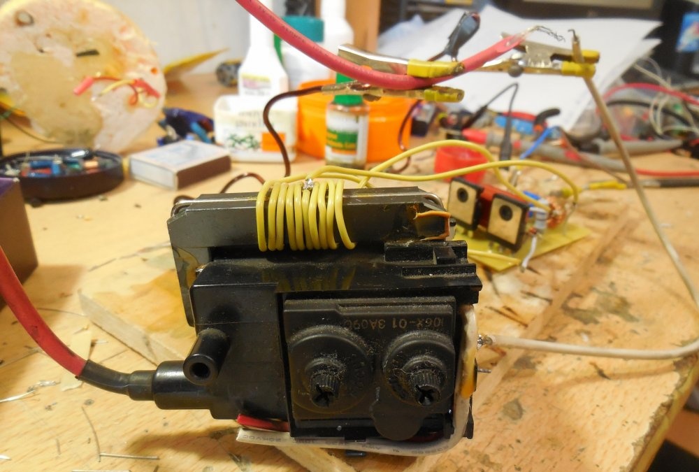
TDKS transformers look like this:
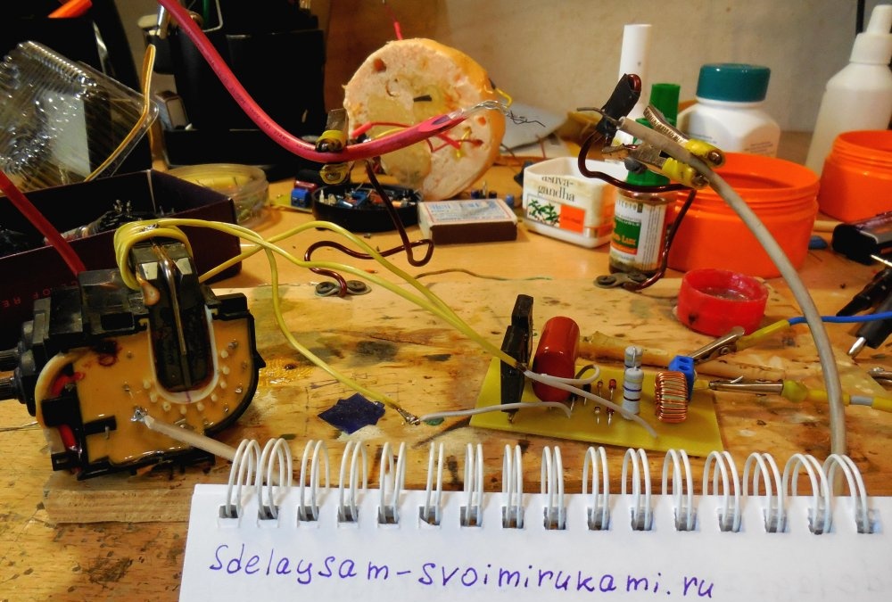
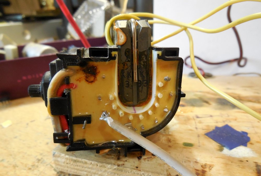
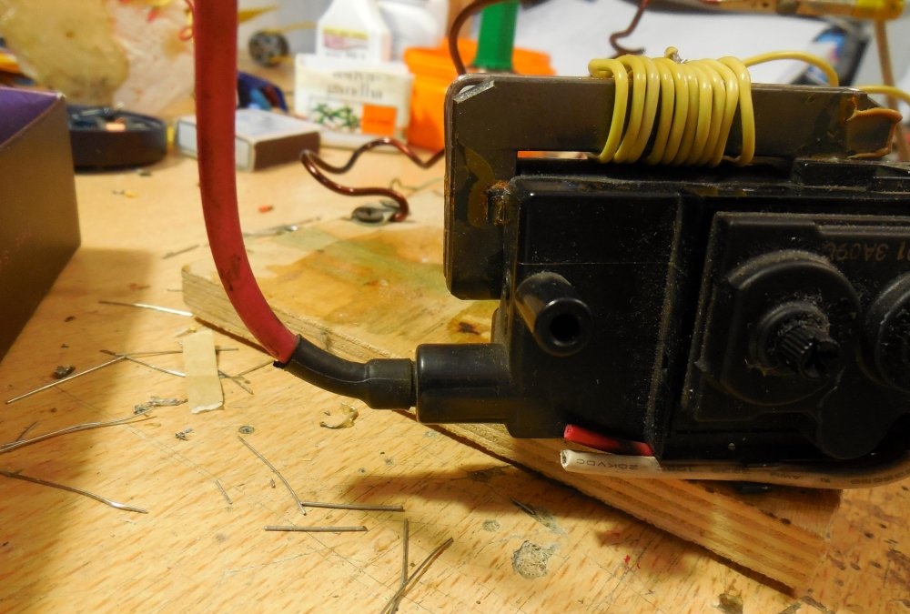
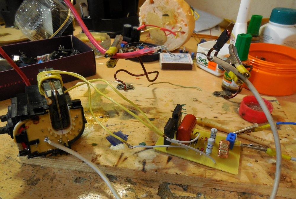
The thick red wire extending from the top of the transformer, as you might guess, is designed to remove high voltage from it.In order to start such a transformer, you need to wind your primary winding around it and assemble a simple circuit called a ZVS driver.
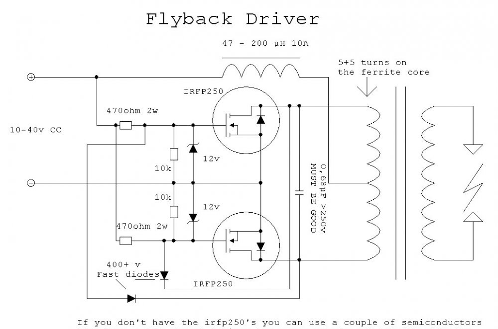
Scheme
The diagram is presented below:
The same diagram in another graphical representation:
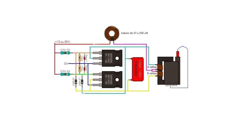
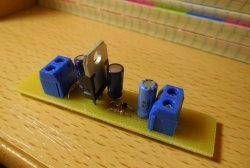
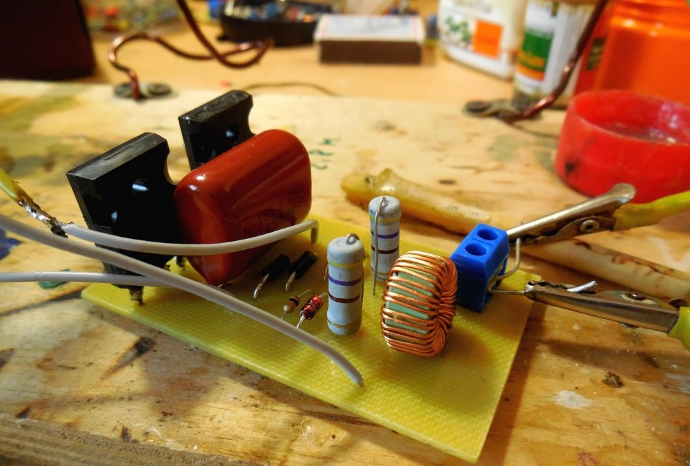
A few words about the scheme. Its key link is IRF250 field-effect transistors; IRF260 are also well suited here. Instead of them, you can install other similar field-effect transistors, but these are the ones that have proven themselves best in this circuit. Between the gate of each transistor and the minus of the circuit, zener diodes are installed for a voltage of 12-18 volts; I installed zener diodes BZV85-C15, for 15 volts. Also, ultra-fast diodes, for example, UF4007 or HER108, are connected to each of the gates. A 0.68 µF capacitor is connected between the drains of the transistors for a voltage of at least 250 volts. Its capacitance is not so critical; you can safely install capacitors in the range of 0.5-1 µF. Quite significant currents flow through this capacitor, so it can heat up. It is advisable to place several capacitors in parallel, or take a capacitor for a higher voltage, 400-600 volts. There is a choke in the diagram, the rating of which is also not very critical and can be in the range of 47 - 200 µH. You can wind 30-40 turns of wire on a ferrite ring, it will work in any case.
Manufacturing
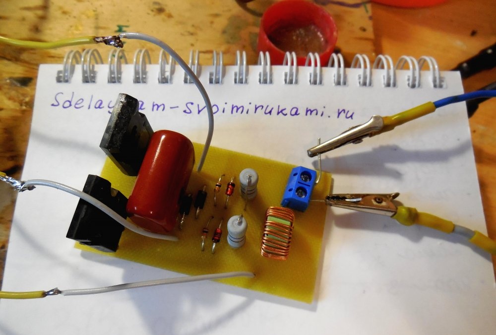
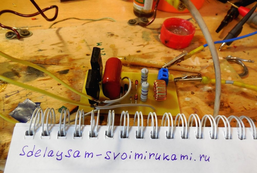
If the inductor gets very hot, then you should reduce the number of turns, or take a wire with a thicker cross-section. The main advantage of the circuit is its high efficiency, because the transistors in it hardly heat up, but, nevertheless, they should be installed on a small radiator for reliability. When installing both transistors on a common radiator, it is imperative to use a heat-conducting insulating gasket, becausethe metal back of the transistor is connected to its drain. The supply voltage of the circuit lies in the range of 12 - 36 volts; at a voltage of 12 volts at idle, the circuit consumes approximately 300 mA; when the arc is burning, the current rises to 3-4 amperes. The higher the supply voltage, the higher the voltage will be at the output of the transformer.
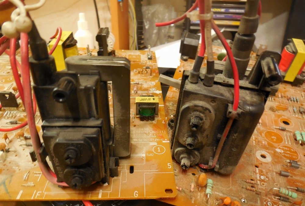
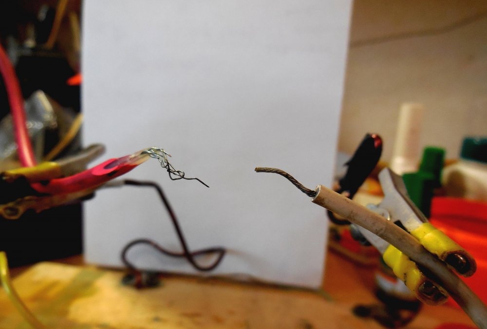
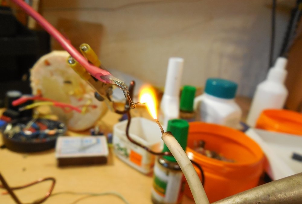
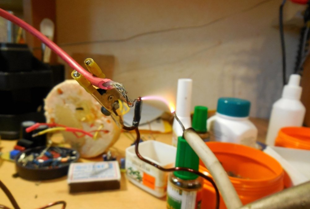
If you look closely at the transformer, you can see the gap between its body and the ferrite core is approximately 2-5 mm. The core itself needs to be wound with 10-12 turns of wire, preferably copper. The wire can be wound in any direction. The larger the wire, the better, but a wire that is too large may not fit into the gap. You can also use enameled copper wire; it will fit into even the narrowest gap. Then you need to make a tap from the middle of this winding, exposing the wires in the right place, as shown in the photo:
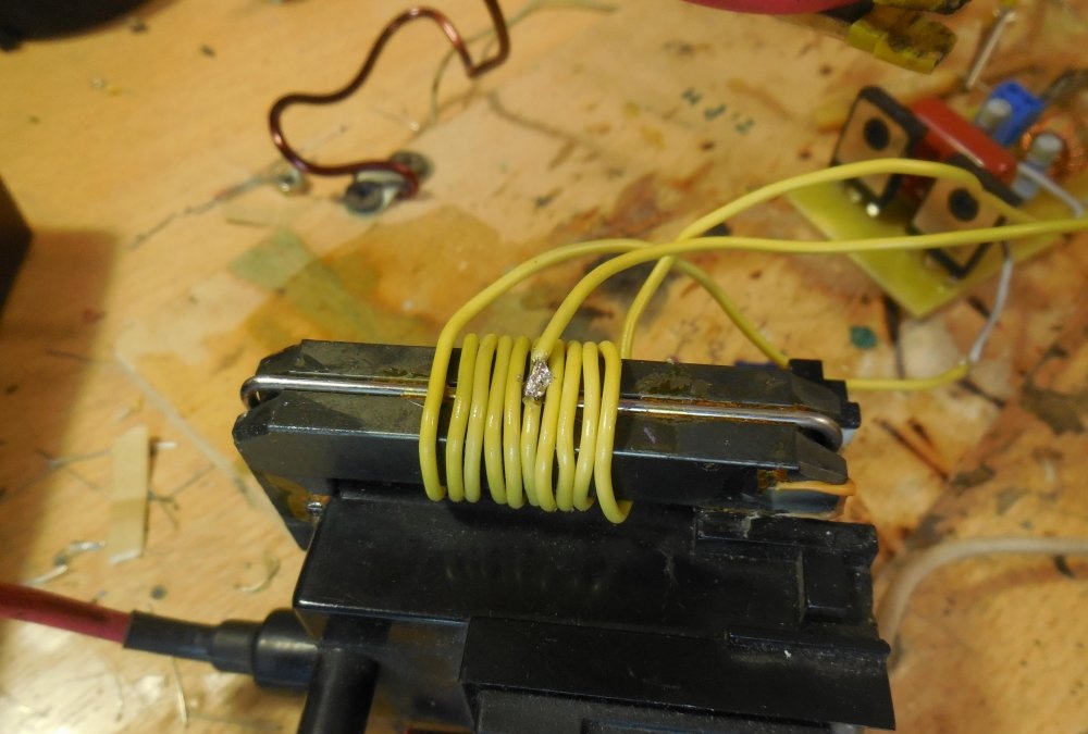
You can wind two windings of 5-6 turns in one direction and connect them, in this case you also get a tap from the middle.
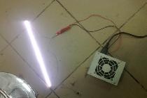
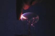
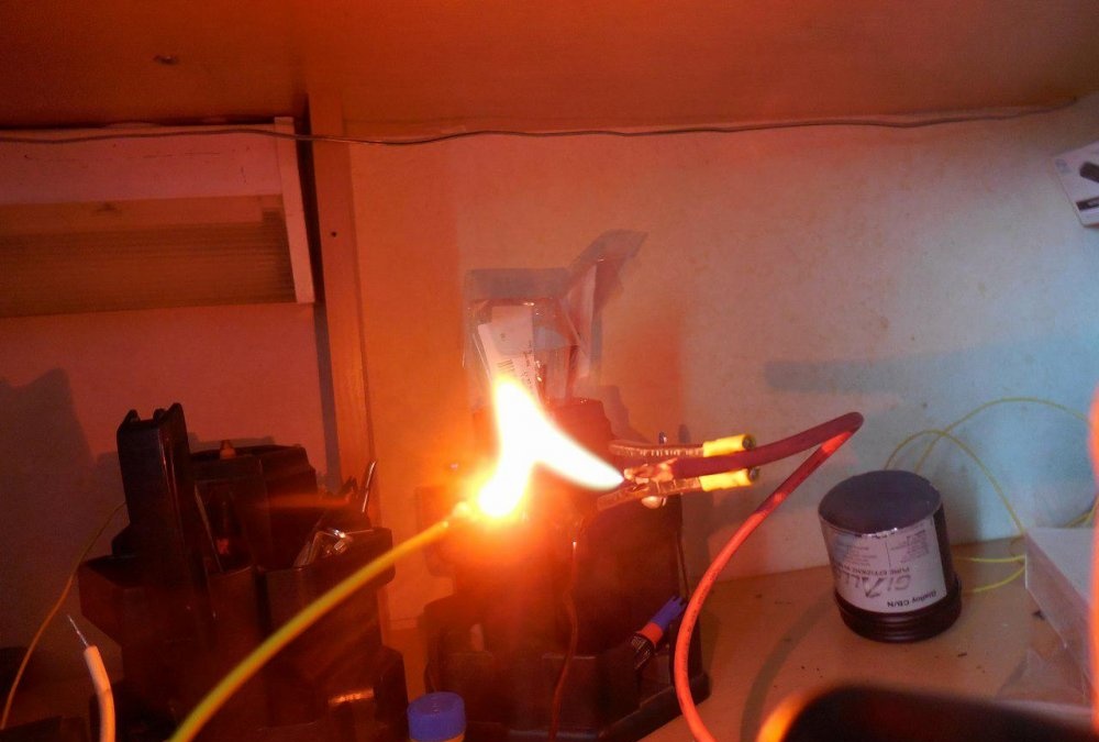
When the circuit is turned on, an electric arc will occur between the high voltage terminal of the transformer (thick red wire at the top) and its negative terminal. The minus is one of the legs. You can determine the required minus leg quite simply by placing the “+” next to each leg in turn. The air breaks through at a distance of 1 - 2.5 cm, so a plasma arc will immediately appear between the desired leg and the plus.
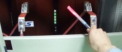
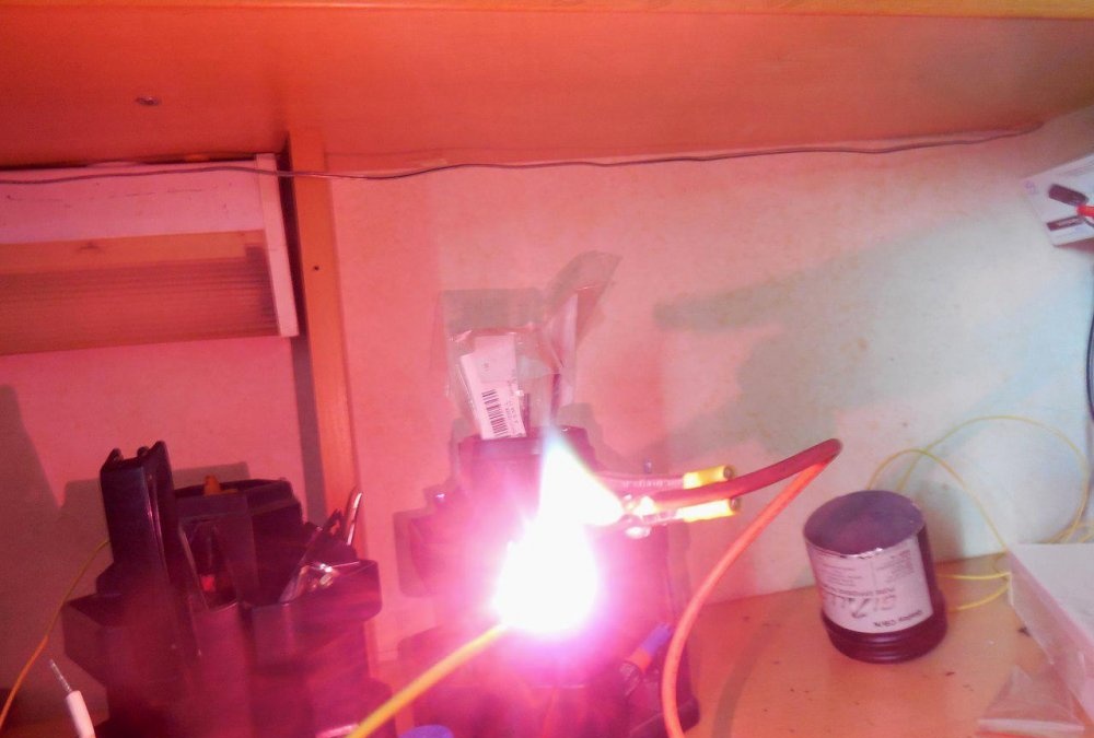
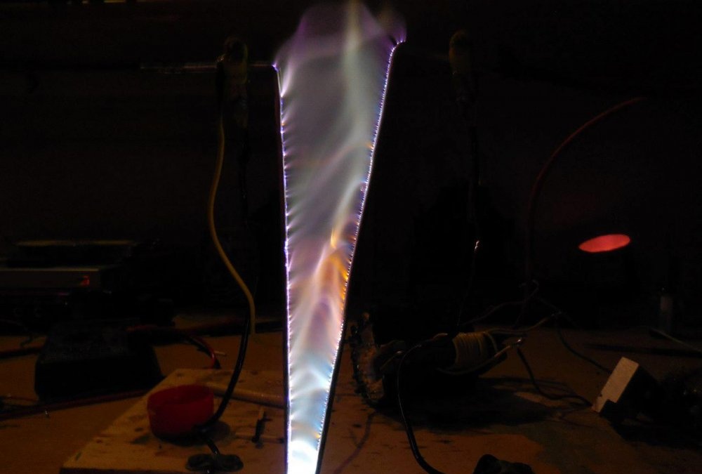
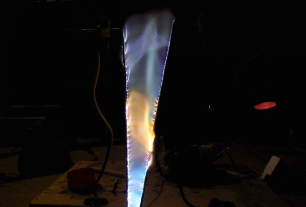
You can use such a high-voltage transformer to create another interesting device - Jacob's ladder. It is enough to arrange two straight electrodes in a “V” shape, connect a plus to one, and a minus to the other. The discharge will appear at the bottom, begin to creep up, break at the top and the cycle will repeat.
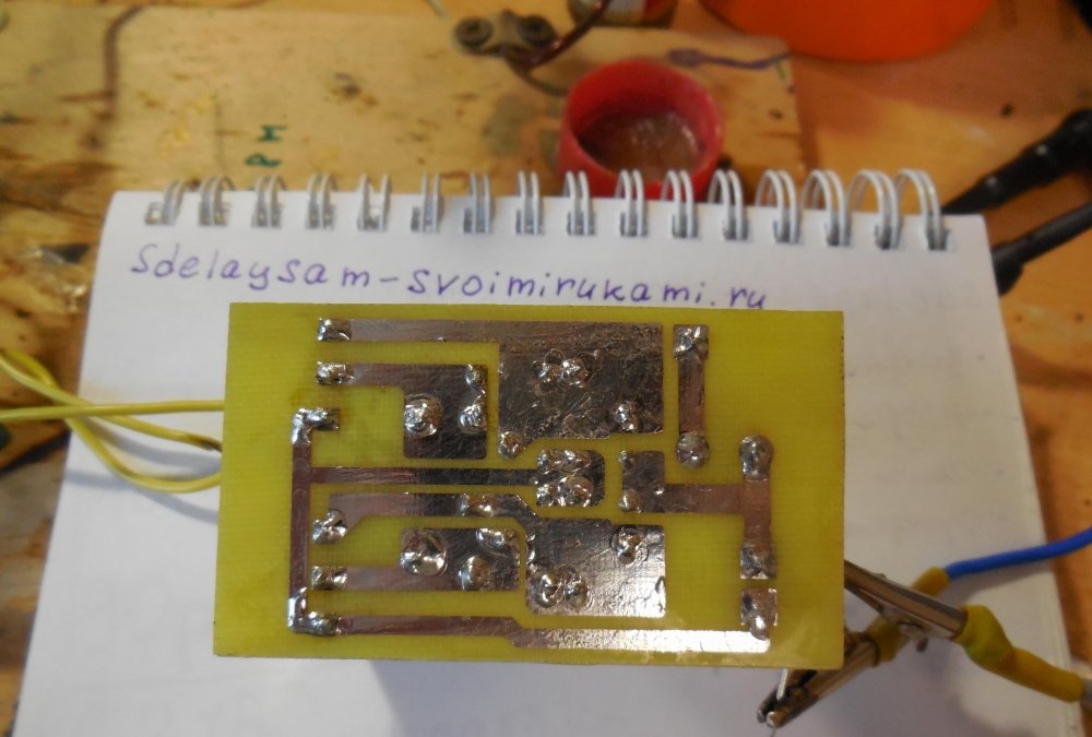
You can download the board here:
Tests
In the photographs, Jacob's ladder looks very spectacular:
The voltage at the output of the transformer is deadly, so safety precautions must be observed. After turning off the power, high voltage continues to be present at the output of the transformer, so it should be discharged by shorting the high-voltage terminals together. Happy build!
Watch test videos
Experiments with high voltage are always very colorful and fascinating.