Do it yourself
Life hacks, master classes, useful tips, recipes.
home » Electronics » DIY power supply » Parametric stabilizer based on a transistor and a zener diode

As you know, no electronic device works without a suitable power source. In the simplest case, a conventional transformer and a diode bridge (rectifier) ​​with a smoothing capacitor can act as a power source. However, a transformer for the required voltage is not always at hand. Moreover, such a power source cannot be called stabilized, because the voltage at its output will depend on the voltage in the network.

An option to solve these two problems is to use ready-made stabilizers, for example, 78L05, 78L12. They are convenient to use, but again they are not always at hand. Another option is to use a parametric stabilizer using a zener diode and a transistor. Its diagram is shown below.

Stabilizer circuit

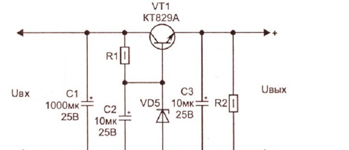
VD1-VD4 in this diagram is a regular diode bridge that converts alternating voltage from the transformer to direct voltage. Capacitor C1 smoothes out voltage ripples, turning the voltage from pulsating to constant.In parallel with this capacitor, it is worth installing a film or ceramic capacitor of small capacity to filter high-frequency ripples, because At high frequencies, the electrolytic capacitor does not do its job well. Electrolytic capacitors C2 and C3 in this circuit are used for the same purpose - smoothing out any ripples. The R1 – VD5 chain serves to form a stabilized voltage, the resistor R1 in it sets the stabilization current of the zener diode. Load resistor R2. The transistor in this circuit absorbs the entire difference between the input and output voltage, so a decent amount of heat is dissipated on it. This circuit is not intended for connecting a powerful load, but, nevertheless, the transistor should be screwed to the radiator using heat-conducting paste.

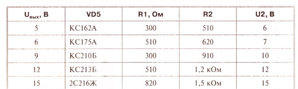
The voltage at the output of the circuit depends on the choice of zener diode and the value of the resistors. Below is a table that shows the ratings of the elements to produce an output of 5, 6, 9, 12, 15 volts.

Parametric stabilizer based on a transistor and a zener diode

Instead of the KT829A transistor, you can use imported analogues, for example, TIP41 or BDX53. It is permissible to install any diode bridge that is suitable for current and voltage. In addition, you can assemble it from individual diodes. Thus, using a minimum of parts, a functional voltage stabilizer is obtained, from which other electronic devices that consume low current can be powered.

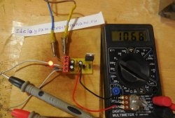
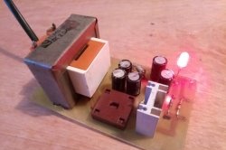
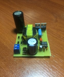
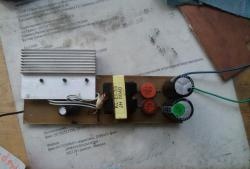
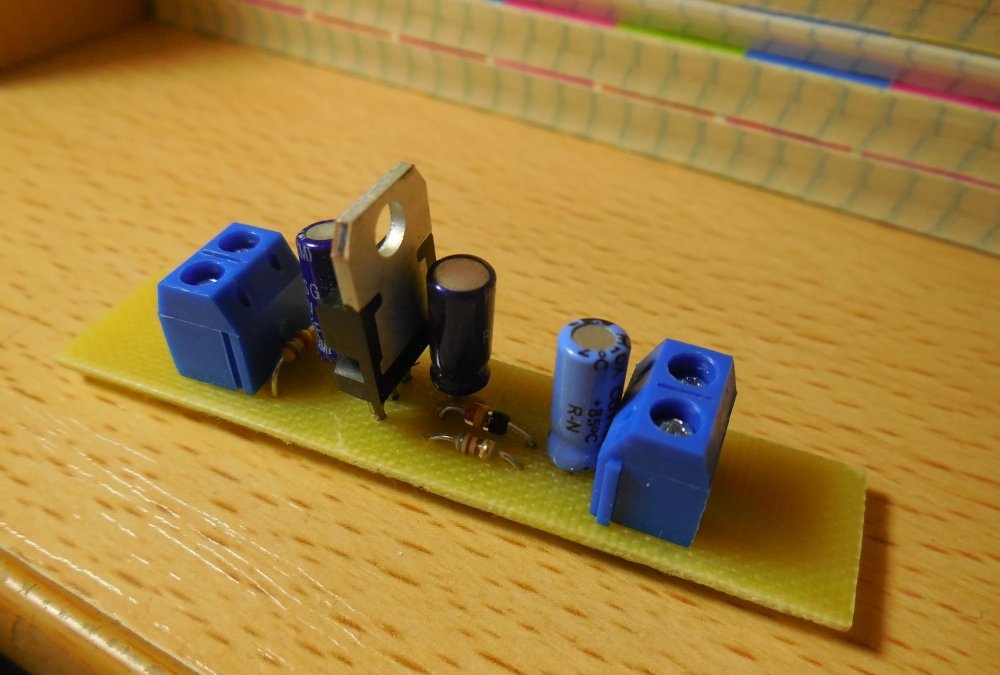
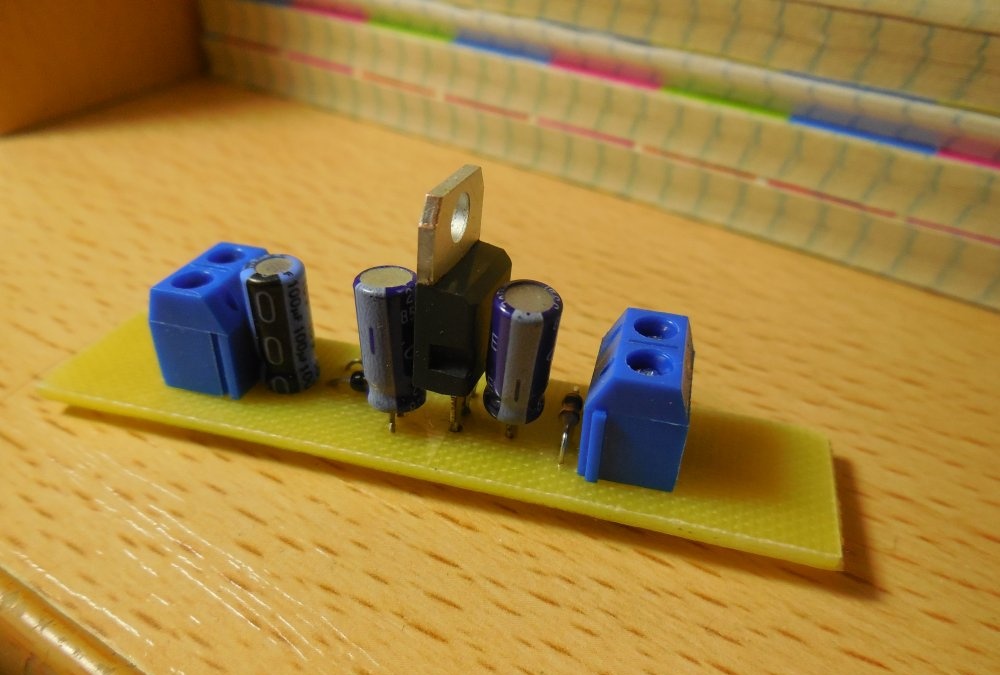
Photo of the stabilizer I assembled:
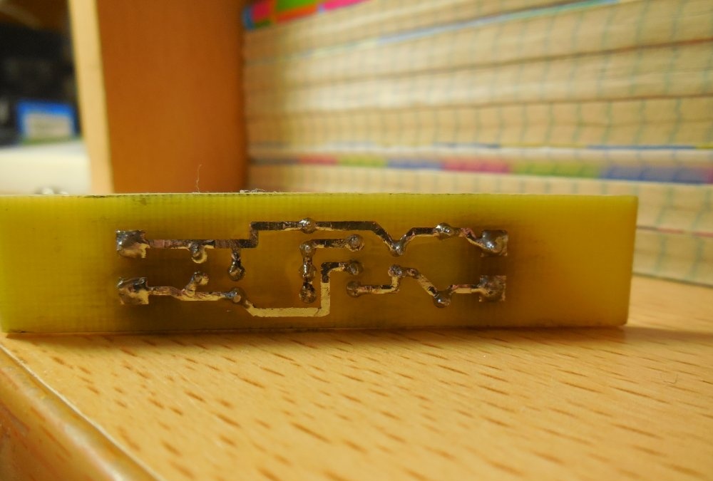
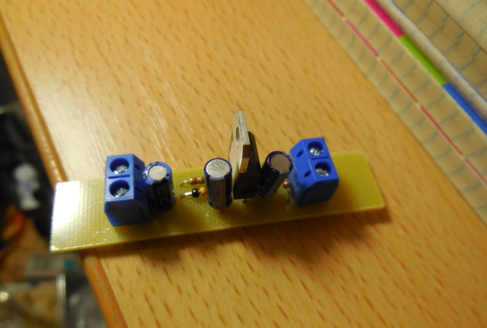
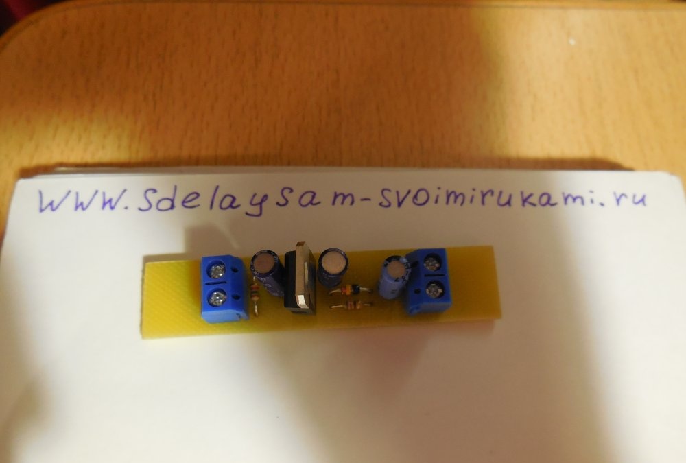
Device board

schema.zip [3.05 Kb] (downloads: 528)

Author – Dmitry S.

come back
Comment
  • bowtiesmilelaughingblushsmileyrelaxed relaxedsmirk
    heart_eyeskissing_heartkissing_closed_eyesflushedrelievedsatisfiedgrin
    winkstuck_out_tongue_winking_eyestuck_out_tongue_closed_eyesgrinningkissingstuck_out_tonguesleeping
    worriedfrowninganguishedopen_mouthgrimacingconfusedhushed
    expressionlessunamusedsweat_smilesweatdisappointed_relievedwearypassive
    disappointedconfoundedfearfulcold_sweatperseverecrysob
    joyastonishedscreamtired_faceangryragetriumph
    sleepyyummasksunglassesdizzy_faceimpsmiling_imp
    neutral_faceno_mouthinnocent
3+three=
Comments (6)
  1. Guest Oleg
    #1 Guest Oleg Guests March 6, 2018 03:43
    4
    Where on the stabilizer diagram are VD1-VD4? What is U2 in the table?
    1. Guest Nikolay
      #2 Guest Nikolay Guests March 26, 2018 00:08
      0
      U2 is the output stabilized voltage when using various zener diodes
  2. Guest Victor
    #3 Guest Victor Guests November 3, 2018 01:04
    0
    Good evening.
    And this stabilizer can withstand a current of 0.5 amps.
    1. Ilya Vasilievich Pozdnyakov
      #4 Ilya Vasilievich Pozdnyakov Guests 7 September 2020 15:00
      0
      This stabilizer will withstand any current. It all depends on the transistor that is used. Another thing is that the higher the current, the more the output voltage will drop
  3. Stanislav
    #5 Stanislav Guests 25 January 2022 15:35
    2
    Thank you for the article! Tell me, what other transistors can be suitable here instead of KT829A? Or maybe there is a specific type of transistor that will definitely fit here?
    1. thousand
      #6 thousand Guests 27 May 2023 07:06
      1
      any composite or 2 pieces regular. The first regulating KT315 and the second power KT 805, etc.

DIY electronics | Page 7

Christmas box | Do it yourself

DIY miniature dart

Cat - toy made of threads | Do it yourself

«Do it yourself - with your own hands» - a site of interesting homemade products made from scrap materials and items at home. Step-by-step master classes with photos and descriptions, technologies, life hacks - everything a real master or just a craftsman needs for needlework. Crafts of any complexity, a large selection of directions and ideas for creativity.

We recommend reading

Washing machine error codes