Multivibrator.
The first circuit is the simplest multivibrator. Despite its simplicity, its scope is very wide. No electronic device is complete without it.
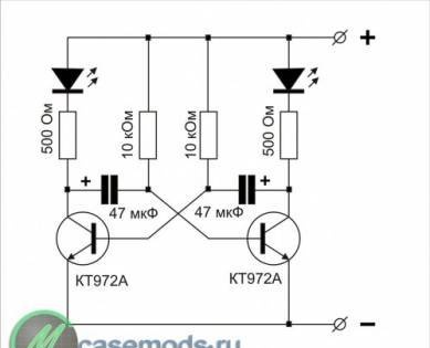
The first figure shows its circuit diagram.
For assembly you will need a minimum of parts:
1. Resistors 500 Ohm - 2 pieces
2. Resistors 10 kOhm - 2 pieces
3. Electrolytic capacitor 47 uF for 16 volts - 2 pieces
4. Transistor KT972A - 2 pieces
5. Light-emitting diode - 2 pieces
KT972A transistors are composite transistors, that is, their housing contains two transistors, and it is highly sensitive and can withstand significant current without heat sink.
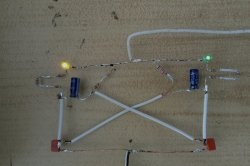
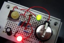
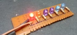
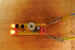
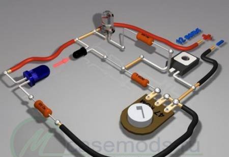
Once you have purchased all the parts, arm yourself with a soldering iron and start assembling. To conduct experiments, you don’t need to make a printed circuit board; you can assemble everything using a surface-mounted installation. Solder as shown in the pictures.
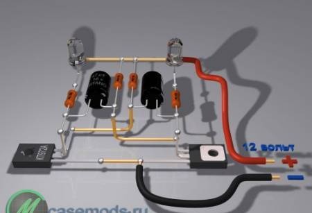
The drawings are specially made from different angles and you can examine in detail all the details of the installation.
Let your imagination tell you how to use the assembled device! For example, instead of LEDs You can install a relay, and use this relay to switch a more powerful load. If you change the values of resistors or capacitors, the switching frequency will change. By changing the frequency you can achieve very interesting effects, from a squeak in the dynamics to a pause for many seconds..
Photo relay.
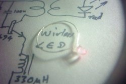
And this is a diagram of a simple photo relay. This device can be successfully used wherever you want, to automatically illuminate the DVD tray, to turn on the light, or to alarm against intrusion into a dark closet. Two schematic options are provided. In one embodiment, the circuit is activated by light, and in the other by its absence.
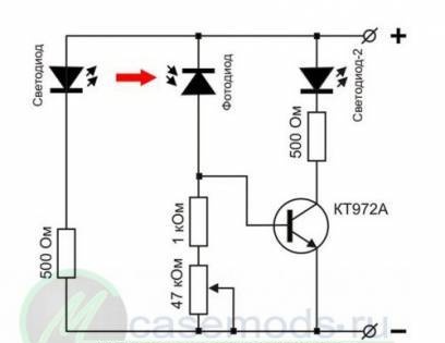
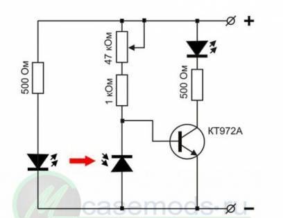
It works like this: when the light is off LED hits the photodiode, the transistor will open and LED-2 will start to glow. The sensitivity of the device is adjusted using a trimming resistor. As a photodiode, you can use a photodiode from an old ball mouse. LED - any infrared LED. The use of infrared photodiode and LED will avoid interference from visible light. Any LED or a chain of several LEDs is suitable as LED-2. An incandescent lamp can also be used. And if you install an electromagnetic relay instead of an LED, you can control powerful incandescent lamps or some mechanisms.
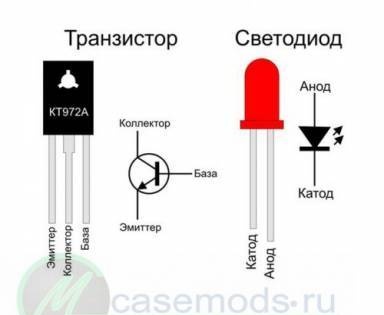
The figures show both circuits, the pinout (location of the legs) of the transistor and LED, as well as the wiring diagram.
If there is no photodiode, you can take an old MP39 or MP42 transistor and cut off its housing opposite the collector, like this:
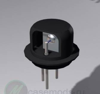
Instead of a photodiode, a p-n junction of a transistor will need to be included in the circuit.You will have to determine experimentally which one will work better.
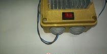
Power amplifier based on TDA1558Q chip.
This amplifier has an output power of 2 X 22 watts and is simple enough for beginner hams to replicate. This circuit will be useful for you for homemade speakers, or for a homemade music center, which can be made from an old MP3 player.
To assemble it you will need only five parts:
1. Microcircuit - TDA1558Q
2. Capacitor 0.22 uF
3. Capacitor 0.33 uF – 2 pieces
4. Electrolytic capacitor 6800 uF at 16 volts
The microcircuit has a fairly high output power and will need a radiator to cool it. You can use a heatsink from the processor.
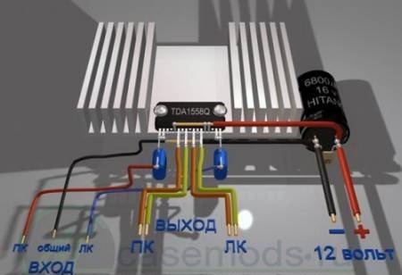
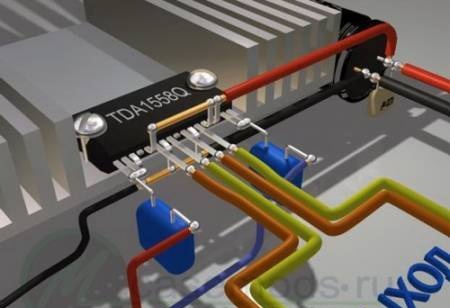
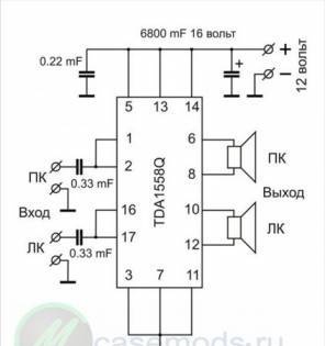
The entire assembly can be done by surface mounting without the use of a printed circuit board. First, you need to remove pins 4, 9 and 15 from the microcircuit. They are not used. The pins are counted from left to right if you hold it with the pins facing you and the markings facing up. Then carefully straighten the leads. Next, bend pins 5, 13 and 14 up, all these pins are connected to the power positive. The next step is to bend pins 3, 7 and 11 down - this is the power supply minus, or “ground”. After these manipulations, screw the chip to the heat sink using thermal conductive paste. The pictures show the installation from different angles, but I will still explain. Pins 1 and 2 are soldered together - this is the input of the right channel, a 0.33 µF capacitor must be soldered to them. The same must be done with pins 16 and 17. The common wire for the input is the minus power supply or ground.
Solder the power plus wire to pins 5, 13 and 14. The same wire is soldered to the positive of the 6800 uF capacitor. Pins 3, 7 and 11 bent down are also soldered together with a wire, and this wire is soldered to the minus of the 6800 uF capacitor.Next, the wires go from the capacitor to the power source.
Pins 6 and 8 are the output of the right channel, pin 6 is soldered to the plus of the speaker, and pin 8 to the minus.
Pins 10 and 12 are the output of the left channel, pin 10 is soldered to the plus of the speaker, and pin 12 to the minus.
The 0.22 µF capacitor must be soldered parallel to the terminals of the 6800 µF capacitor.
Before applying power, carefully check the installation for correct installation. At the amplifier input you need to install a dual 100 kOhm variable resistor to adjust the volume.