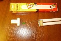
This converter is incredibly easy to manufacture; it contains only 1 transistor. Made entirely from parts from an old computer power supply board. Can be used to power various LED lamps, LED strips, various devices, etc.
Will need
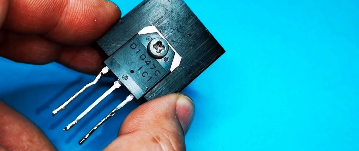
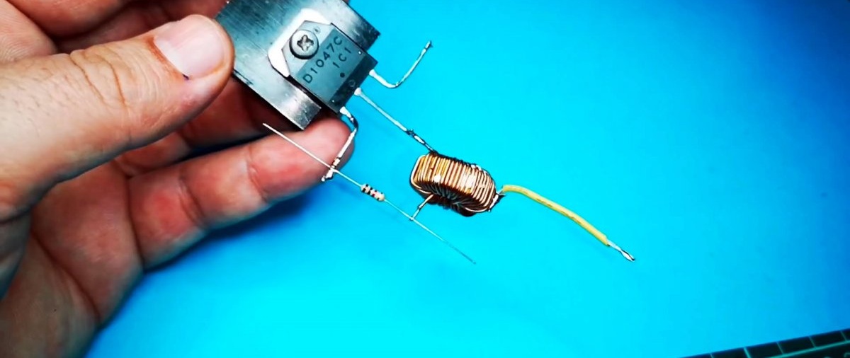
- Transistor D1047C (Almost any bipolar one will do) -

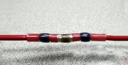
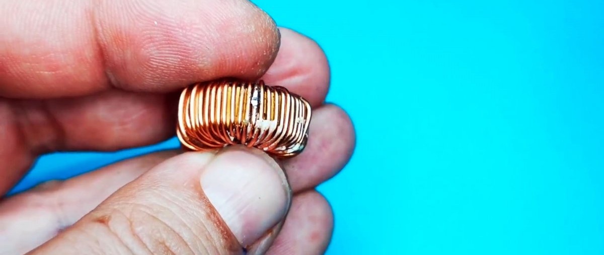
- Inductor.
- Resistor 1 kOhm.
- Diode.
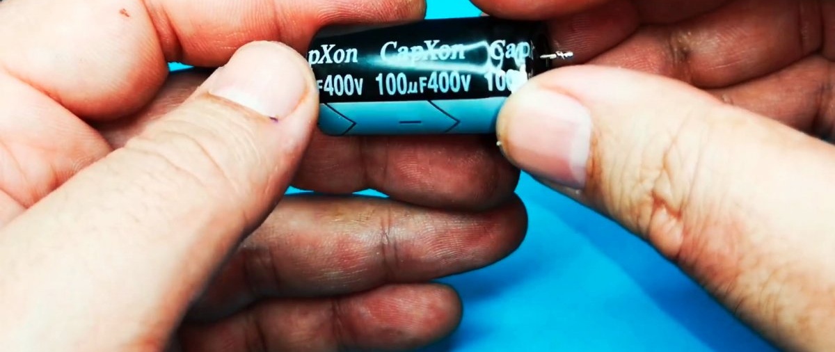
- Capacitor 100 uF 400 V.

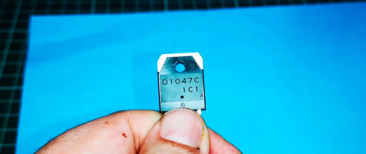
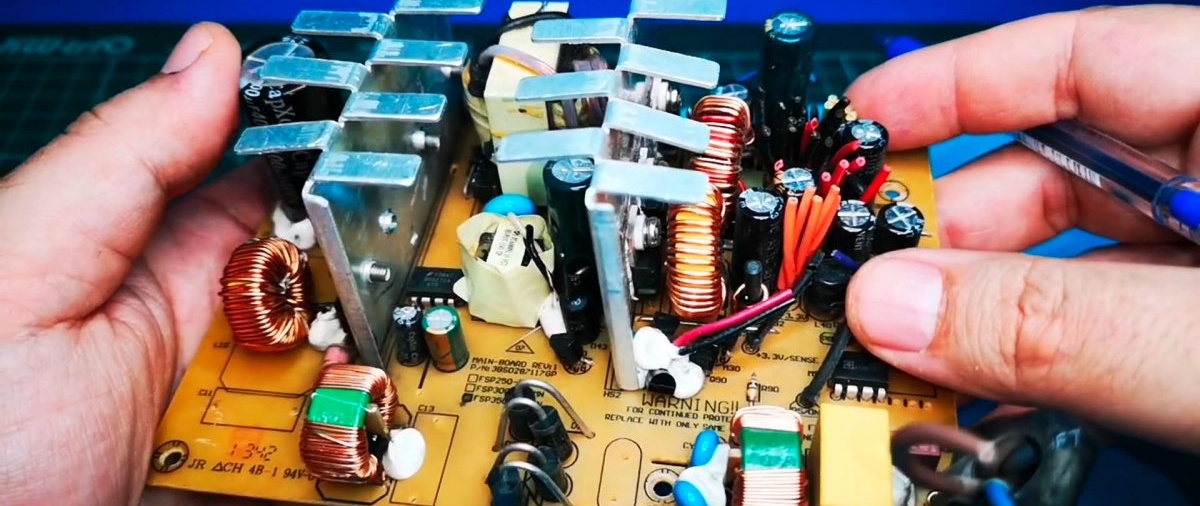
All parts can be found on the computer power supply.
Scheme
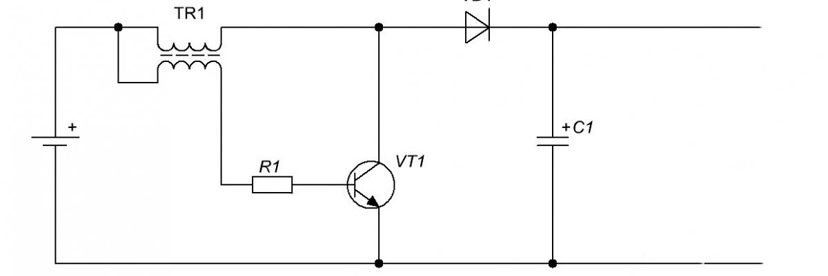
The simplest circuit using a single transistor with self-excitation. At the output, you can install a zener diode as a diode and then the output voltage will be stabilized to the specified value.
The coil is used ready-made. If you are planning to do it yourself, then take a 0.7 mm wire. The number of turns is 45 with a tap from 30 turns.
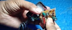
Making a DC-DC converter with your own hands
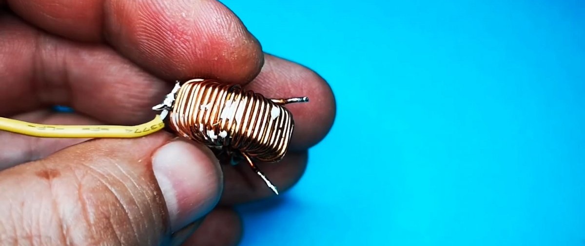
We solder the inductor using similar parameters.
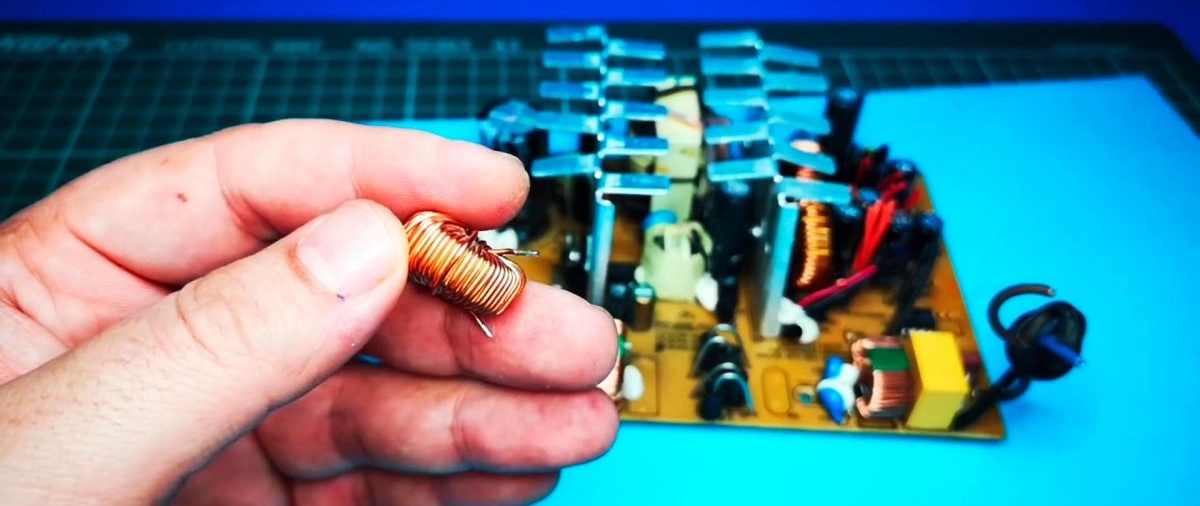
It doesn’t have a branch from the middle, so we’ll make one ourselves. Having counted the approximate ratio of turns, use a utility knife to scrape off the varnish at the soldering site.
Solder the wire and the middle pin is ready.
We install the transistor on the radiator.
Solder the inductance.
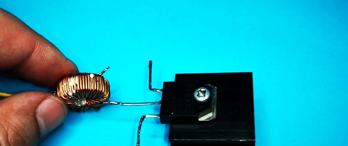
Solder the resistor.
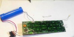
Solder the diode, capacitor, wires.
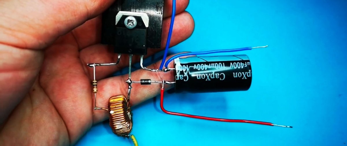
At this point the converter is ready for operation.
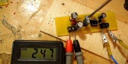
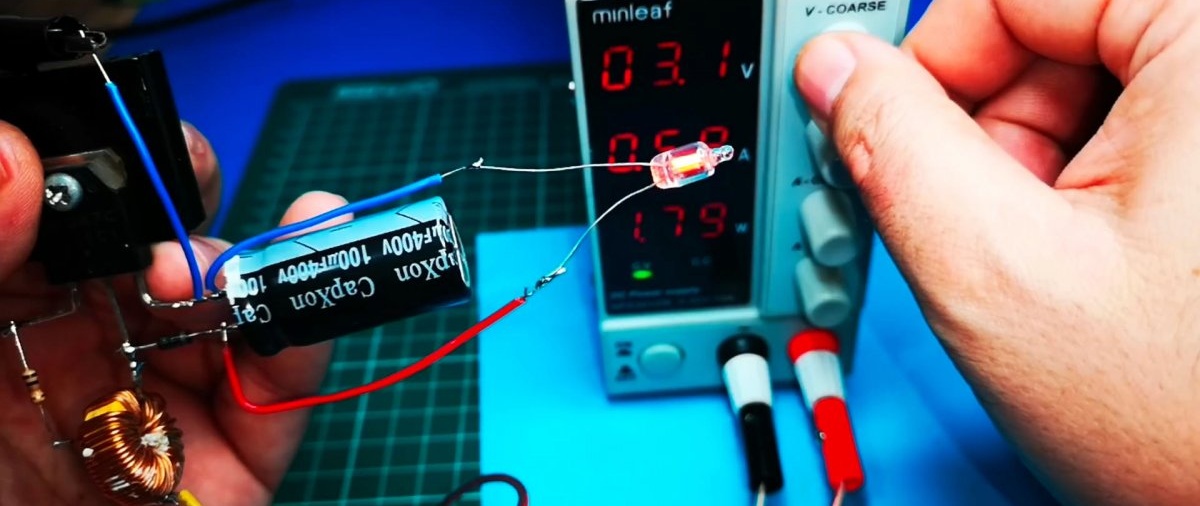
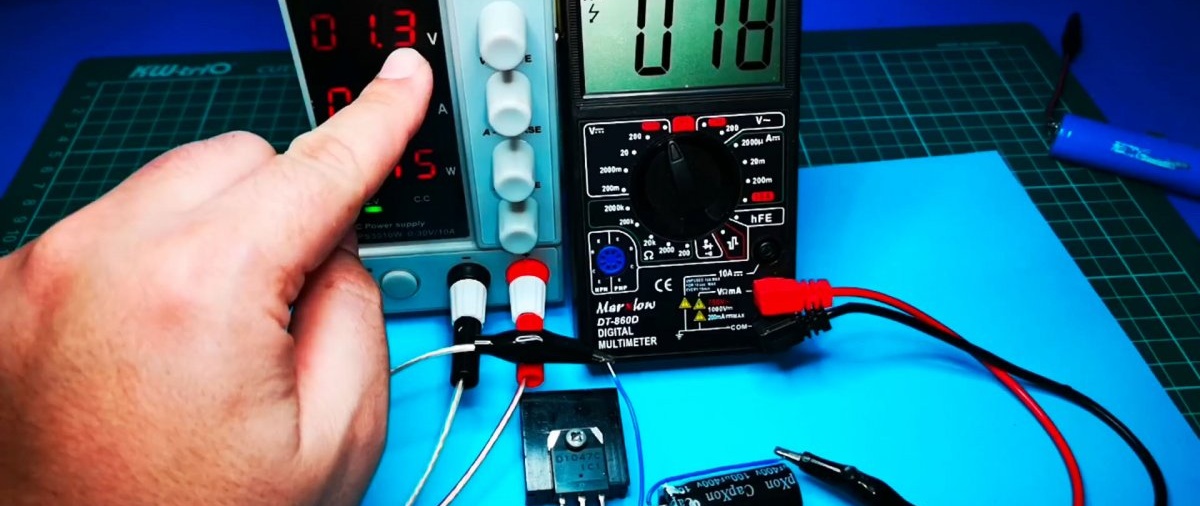
Testing the converter in action
We apply a voltage of 1.3 V. And at the output we already have 18 V.
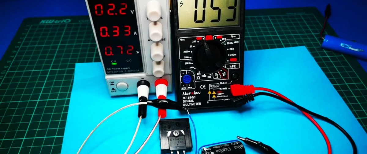
We increase the voltage to 2.2 V and the output is about 50 V
With a 4.4 V input, this results in more than 150 V.
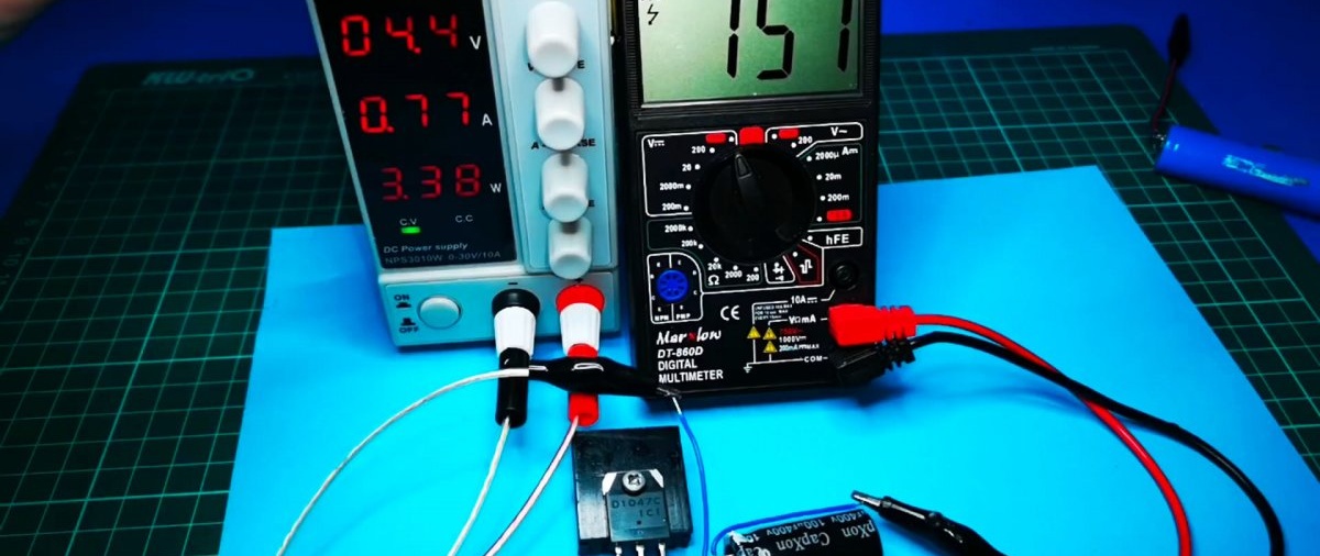
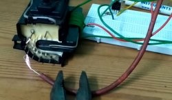
We try it on a small load, in the form of which a neon lamp is used.

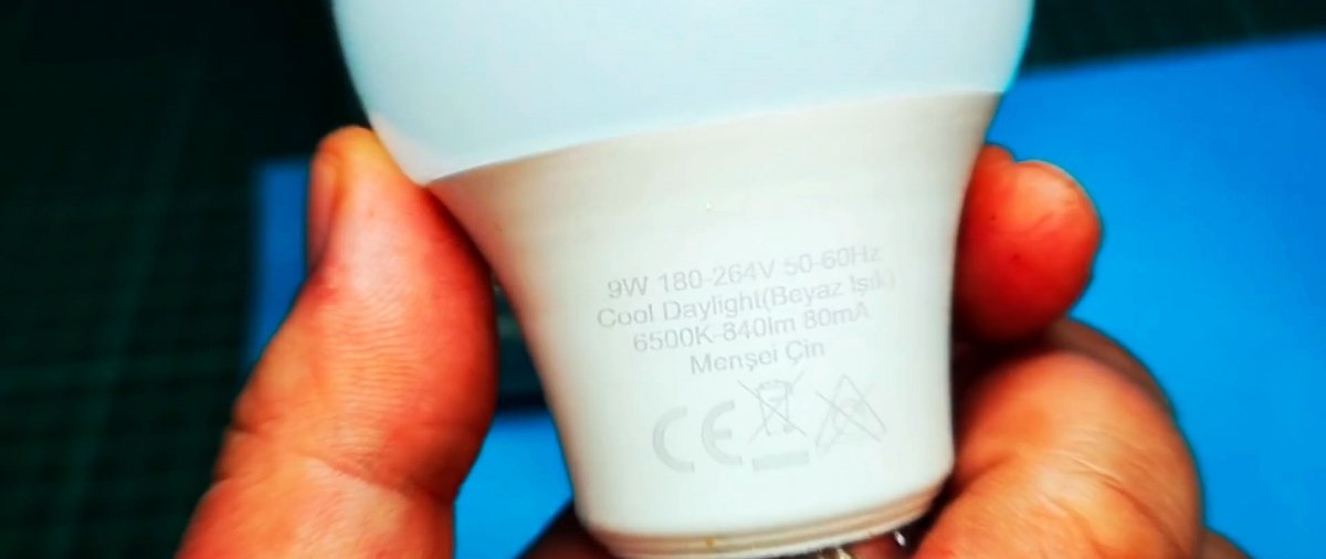
Now let's test the converter on a more realistic load - an LED lamp.
The converter powers the lamp well at 5 V.
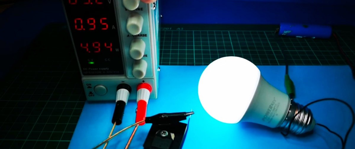
The converter efficiency is about 98%, power consumption is about 5 W.