Pulse DC-DC converters are designed for both increasing and decreasing voltage. With their help, you can convert 5 volts, for example, into 12, or 24, or vice versa, with minimal losses. There are also high-voltage DC-DC converters; they are capable of obtaining a very significant potential difference of hundreds of volts from a relatively low voltage (5-12 volts). In this article we will consider the assembly of just such a converter, the output voltage of which can be adjusted within 60-250 volts.
Converter circuit
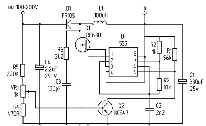
It is based on the common NE555 integrated timer. Q1 in the diagram is a field-effect transistor; you can use IRF630, IRF730, IRF740 or any others designed to operate with voltages above 300 volts. Q2 is a low-power bipolar transistor, you can safely install BC547, BC337, KT315, 2SC828. Choke L1 should have an inductance of 100 μH, however, if this is not at hand, you can install chokes in the range of 50-150 μH, this will not affect the operation of the circuit. It’s easy to make a choke yourself - wind 50-100 turns of copper wire on a ferrite ring.Diode D1 according to the FR105 circuit; instead, you can install UF4007 or any other high-speed diode with a voltage of at least 300 volts. Capacitor C4 must be high-voltage, at least 250 volts, more possible. The larger its capacity, the better. It is also advisable to install a small-capacity film capacitor in parallel with it for high-quality filtering of high-frequency interference at the output of the converter. VR1 is a trimming resistor with which the output voltage is regulated. The minimum supply voltage for the circuit is 5 volts, the most optimal is 9-12 volts.
Converter manufacturing
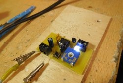
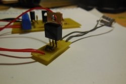
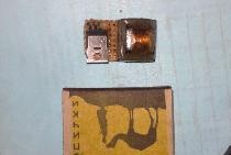
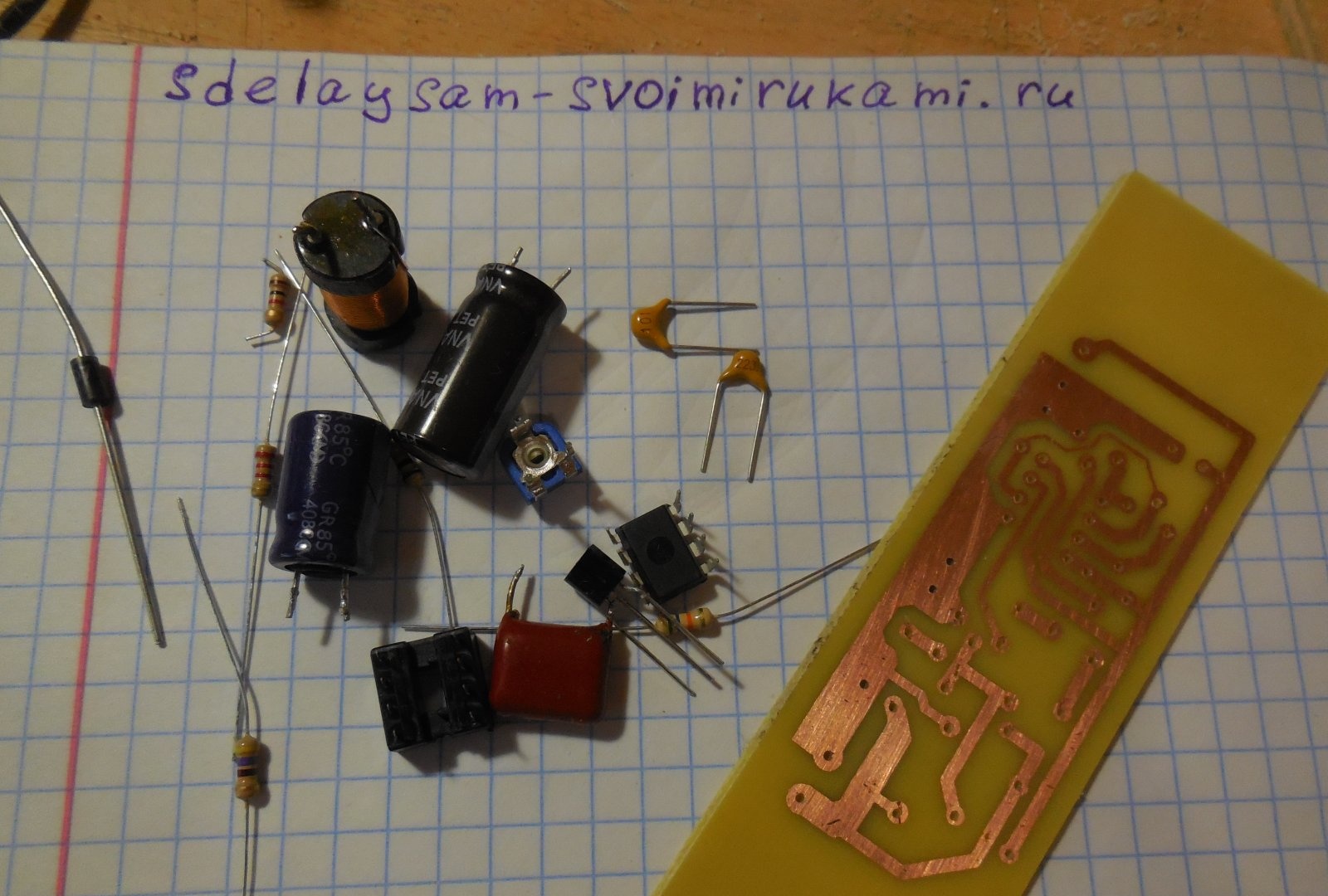
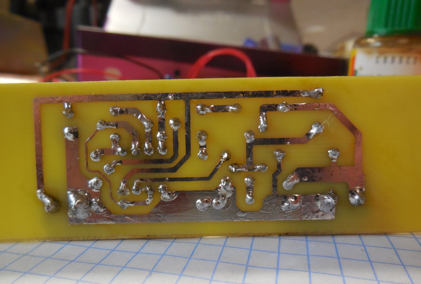
The circuit is assembled on a printed circuit board measuring 65x25 mm; a file with a drawing of the board is attached to the article. You can take a textolite larger than the drawing itself, so that there is room at the edges for attaching the board to the case. A few photos of the manufacturing process:
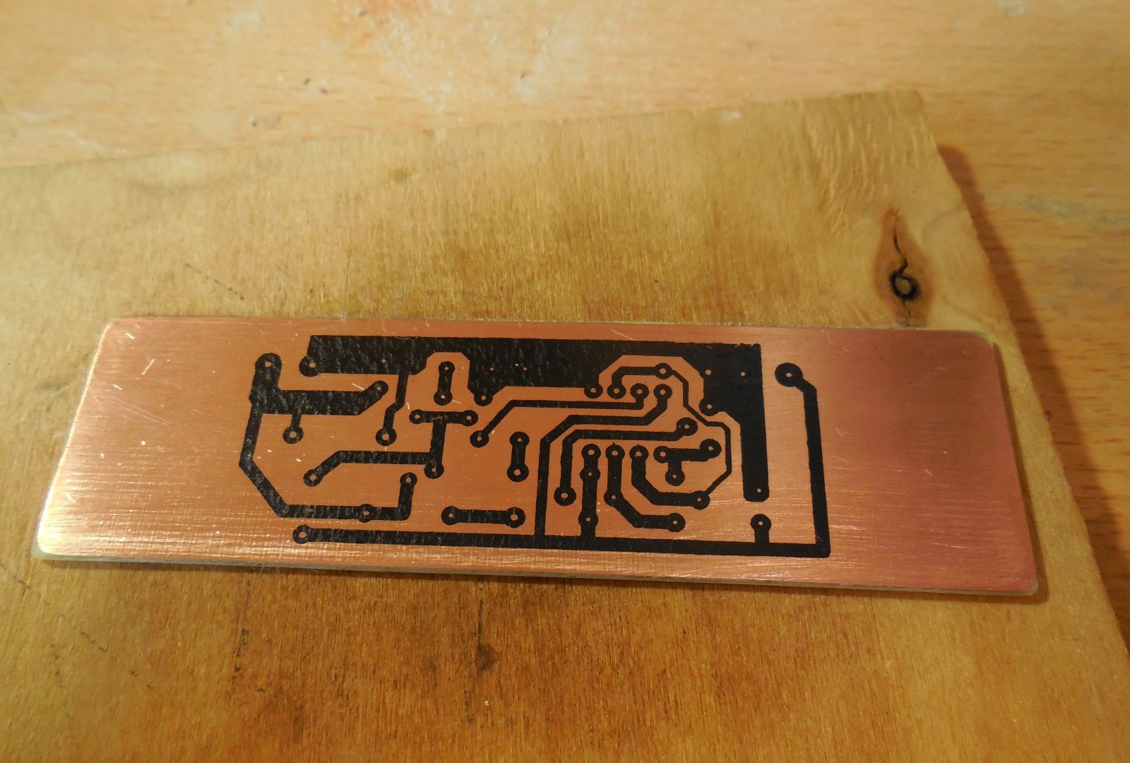
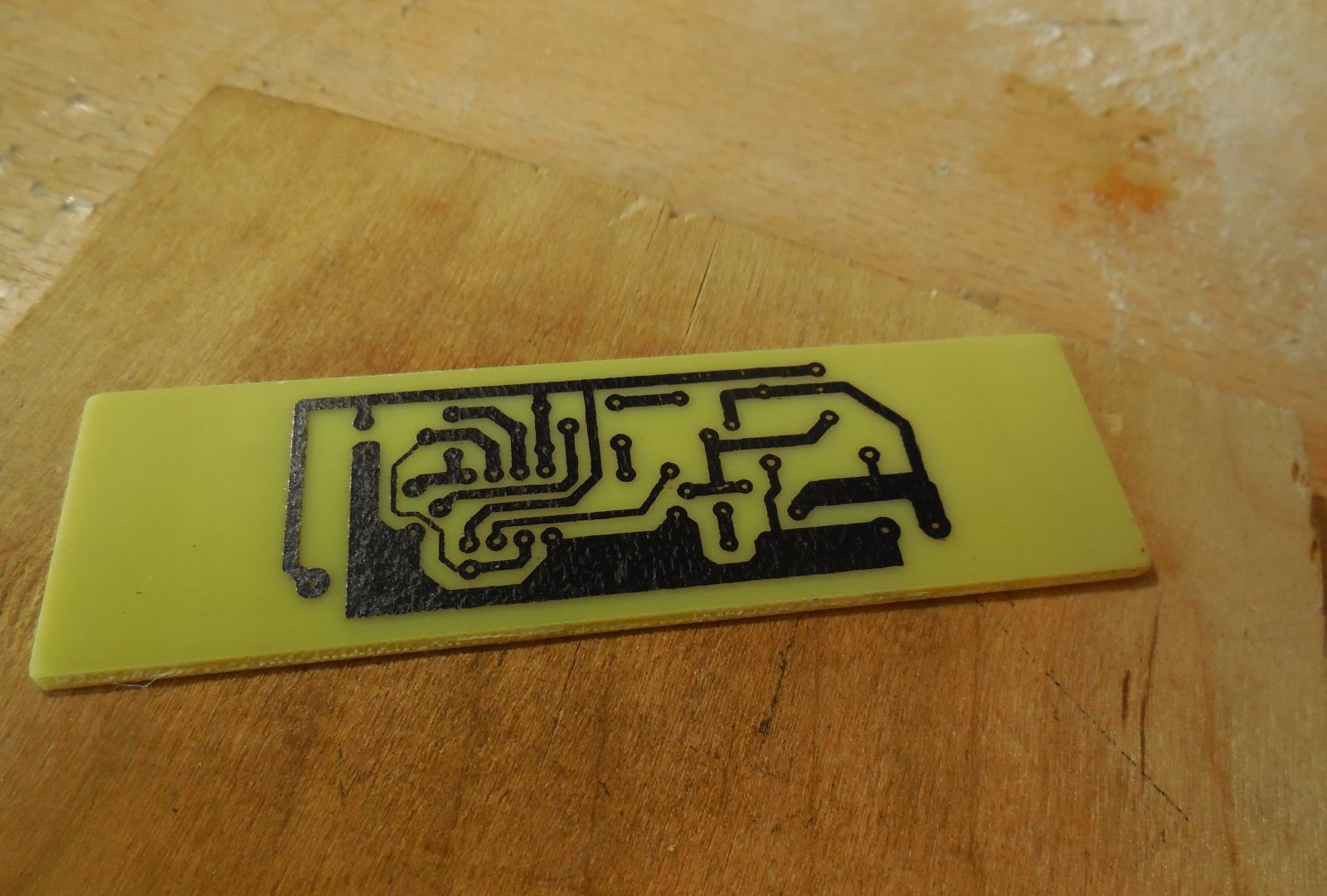
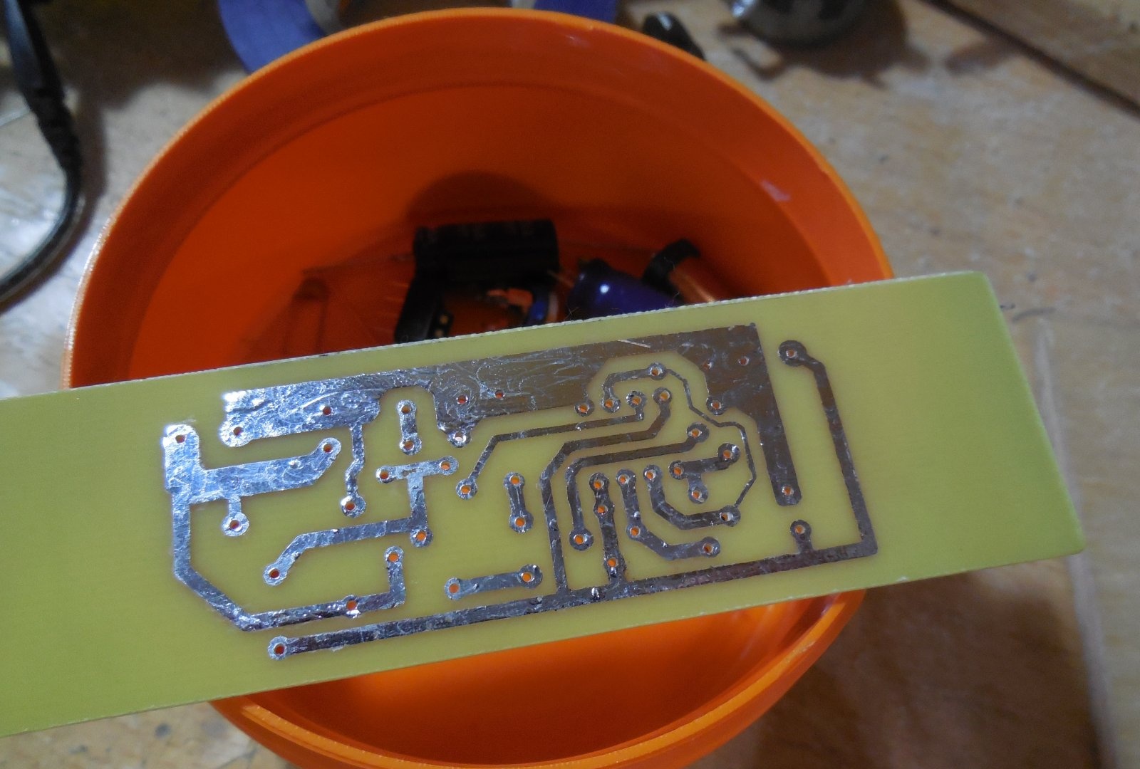
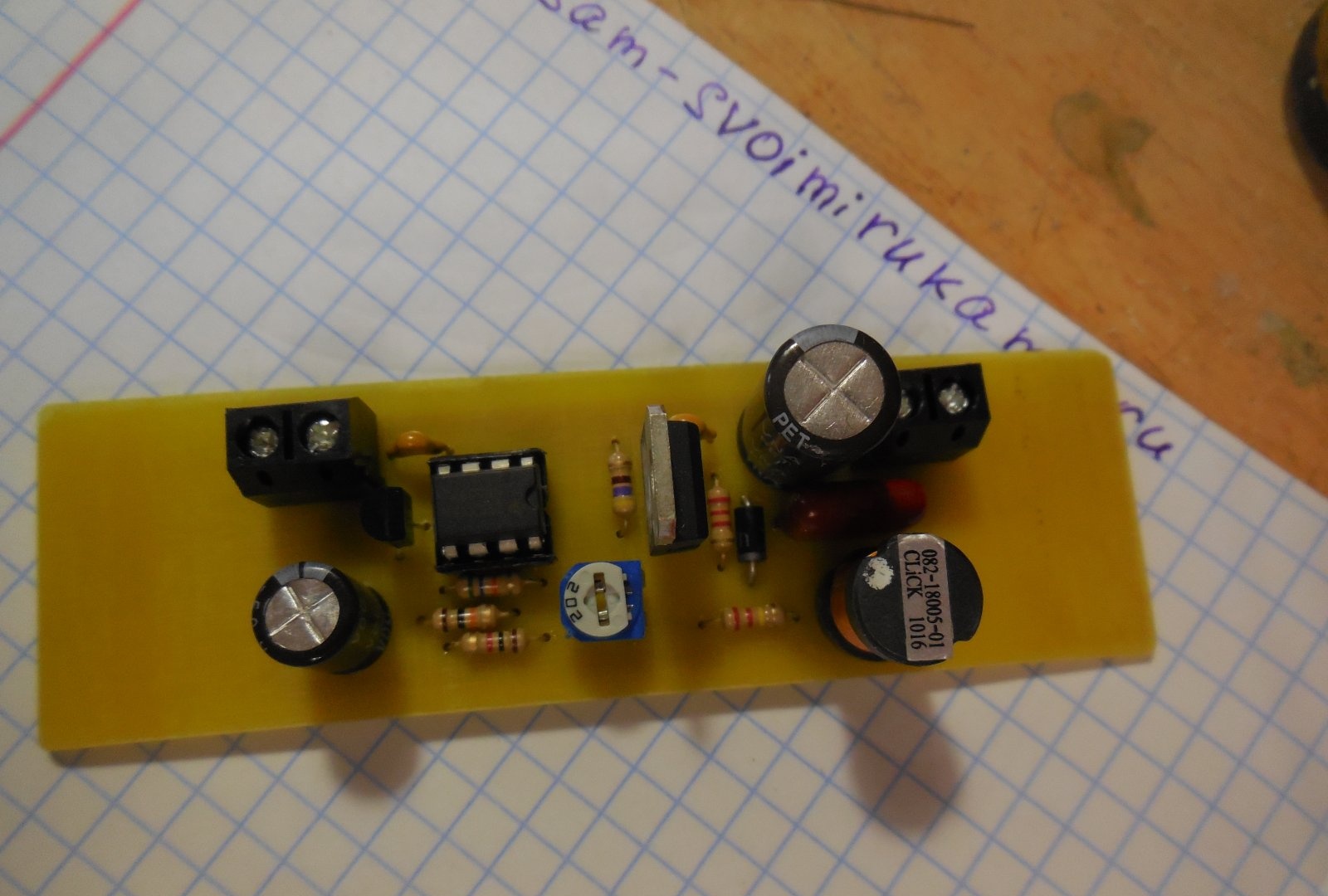
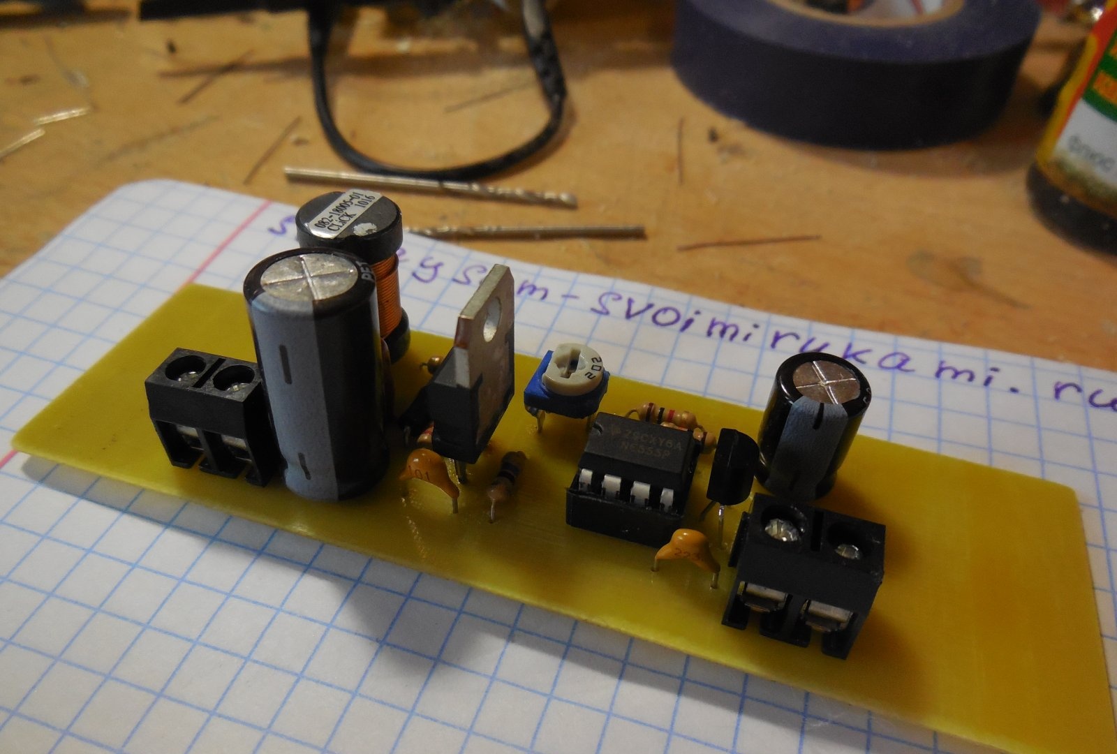
After etching, the board must be tinned and checked for short circuits. Because There is high voltage on the board; there should be no metal burrs between the tracks, otherwise a breakdown is possible. First of all, small parts are soldered onto the board - resistors, diode, capacitors. Then the microcircuit (it is better to install it in the socket), transistors, trimming resistor, inductor. To make it easier to connect wires to the board, I recommend installing screw terminal blocks; places for them are provided on the board.
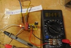
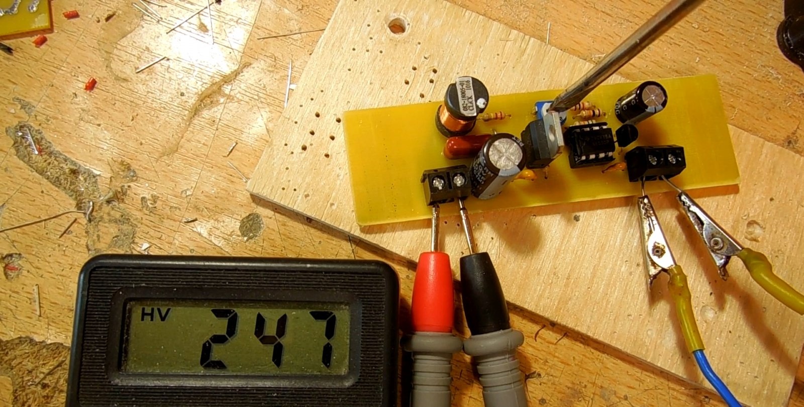
First launch and setup
Before starting, be sure to check the correct installation and ring the tracks. Set the trimming resistor to the minimum position (the slider should be on the side of resistor R4).After this, you can apply voltage to the board by connecting an ammeter in series with it. At idle, the current consumption of the circuit should not exceed 50 mA. If it fits within the norm, you can carefully turn the trimming resistor, controlling the output voltage. If everything is fine, connect a load, for example, a 10-20 kOhm resistor to the high-voltage output and test the operation of the circuit again, this time under load.
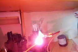
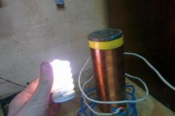
The maximum current that such a converter can produce is approximately 10-15 mA. It can be used, for example, as part of lamp technology to power lamp anodes, or to light gas-discharge or luminescent indicators. The main application is a miniature stun gun, because the output voltage of 250 volts is noticeable to a person. Happy building!
The operation of the converter is clearly demonstrated in the video: