Stethoscopes are associated primarily with medical devices used to diagnose diseases based on the sounds of the lungs and heart. However, in addition to this, they are widely used in other areas, for example, they are used by auto mechanics to listen to extraneous sounds when the engine is running. And if the stethoscope has great sensitivity, then by attaching its sensor to the wall, you can easily hear the conversation of people on the other side of the wall - however, it is worth remembering that eavesdropping on other people’s conversations is prohibited, and simply immoral. The presented stethoscope circuit actually has high gain, providing good sensitivity, especially with a good sensor.
Description of the circuit
The first two stages of the stethoscope use a low-noise operational amplifier OPA350, which is very important, because excess noise in the audio path will make the useful signal less intelligible. The OPA350 indicated in the diagram is quite expensive; you can replace it with the cheap and affordable NE5532, which is also considered low-noise, albeit with degraded parameters - that’s exactly what I did.The gain is determined by the value of resistor R18 in the feedback circuit of the amplifier; a value of 10 MOhm may even be excessive; if self-excitation occurs or simply excessive sensitivity, it can be reduced.

At the output of the operational amplifier there is a variable resistor - a volume control. Practice has shown that the required volume is achieved even with a small angle of rotation of the regulator from the minimum. Next in the diagram is an amplitude-frequency response control unit and a corresponding regulator; with its help, you can adjust the amplitude-frequency response of the signal in the high-frequency region, which in some cases will help make the received signal more legible. The last transistor houses a repeater that switches the headphones, shown in the diagram as a dynamic head. The output of the circuit is mono, and the headphones have input for the right and left channels; they are simply connected in parallel. It makes no sense to use a circuit with a speaker connected at the output, since it will not be possible to get rid of acoustic feedback, given the very high gain of the circuit. Sometimes an acoustic connection occurs even with headphones if they are close to the sensor.
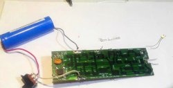
The supply voltage of the circuit is 9..12 volts, and it is important that the power source is as clean as possible and does not produce pulsations at the output, since they can easily get into the sound signal of the stethoscope. Therefore, a good source, in this case, would be a 9-volt battery, given the low current consumption of the circuit.
You can download the board here:Stethoscope sensor
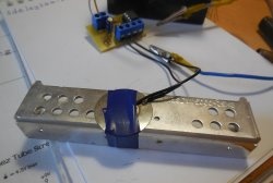
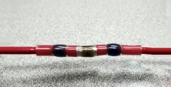
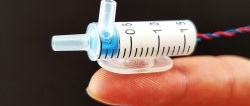
In the diagram, the sensor is designated as “Micro1” and is located in the very left part of it. A piezoplate will be used as a sensor - the most common squeaker, which is found in many toys, multimeters and other electronics.Its brass substrate is soldered to the ground of the circuit, and the piezoelectric crystal itself is soldered to the input. When soldering piezoelectric plates, you should be careful, as they lose their properties when heated. Different piezoelectric plates can give different results in terms of sensitivity; large specimens (4 cm in diameter) showed good results; also, according to some information, excellent sensitivity is given by the domestic ZP-3 and others from this series. The piezoelectric plate can be used in its bare form, gluing it with double-sided tape to the object that needs to be listened to, or you can make a full-fledged sensor out of it, mounting it in the housing and making a spring-loaded pickup needle - this will give a good increase in sensitivity. The piezoelectric plate is soldered to the input of the circuit with a flexible shielded wire; I use MGTFE for this.

Assembly of the structure
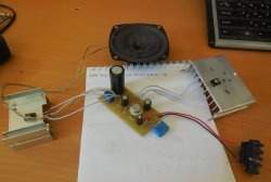
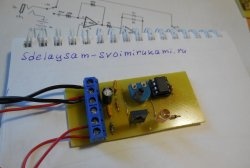
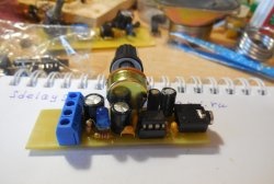
The stethoscope is assembled on a fairly spacious printed circuit board, which will be included in the archive. The printed circuit board involves the use of output elements, except for the operational amplifier - it is in an SMD package.


The printed circuit board was made using the usual LUT method, which has been repeatedly described on the Internet. Variable resistors are soldered directly onto the board, next to them there are 3.5 mm sockets for connecting a headphone plug (output) and a piezoelectric plate (input), power is supplied through two wires. An assembled board without a housing will do a good job of picking up interference, especially when approaching network wires. To avoid this, the board can be placed in a metal case, which is connected to the ground of the circuit, and only the shielded wire to the sensor can be brought out.The assembled stethoscope has really good characteristics; with its help, you can clearly hear the conversation of people through a thin wall, even when using a primitive sensor.