LED signal strength indicators have been around for decades. In middle-class sound-reproducing equipment, they have almost completely replaced other level control devices: pointers, LCD matrices. The reason is the simplicity and low cost of the design and good optical performance. However, there are options for LED indicators of a very complex and advanced design, including those with microprocessor control. But in this article we will not delve into complex schemes. Let’s make an indicator with our own hands, which probably couldn’t be simpler.

Will need
- LEDs - 10 pieces.
- Diodes 1N4007 - 10 pieces.
- Resistors 470 Ohm - 10 pieces.
- Capacitors 470 uF 16 V - 2 pieces.
To be completely honest, this design cannot be fully called a level indicator. There can be no talk of any precise measurements in this homemade product. Rather, we can say that this is simply a decoration of the equipment - LEDs will flash to the beat of the music. Like on early cheap Chinese radios, if anyone else remembers them.Our indicator will be assembled without the use of transistors and microcircuits, without making a printed circuit board - by surface mounting. Begin.
Making a simple level indicator
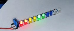
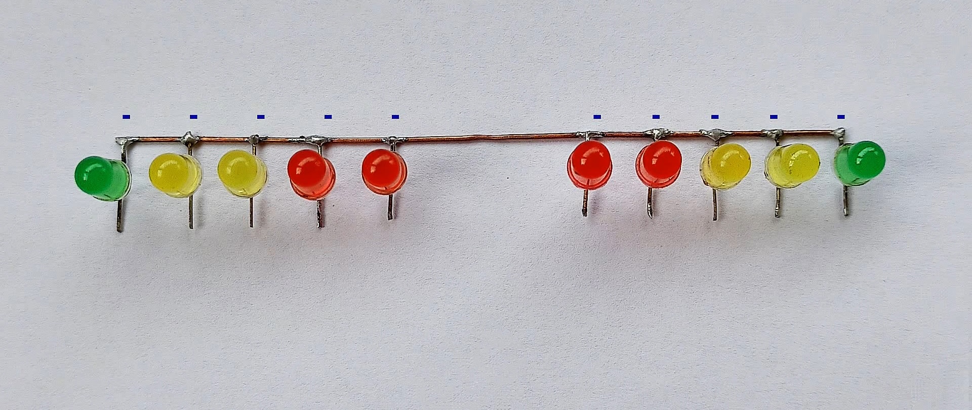
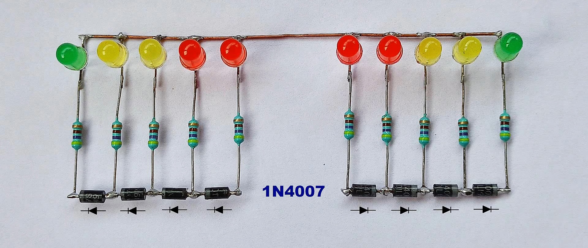
Our indicator will be “pseudo-two-channel”. So, quantity and colors LEDs We choose accordingly - in pairs. Two pairs of red, two pairs of yellow and the same number of green.

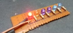
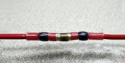
By placing LEDs Accordingly, we connect their negative terminals to each other using soldering.
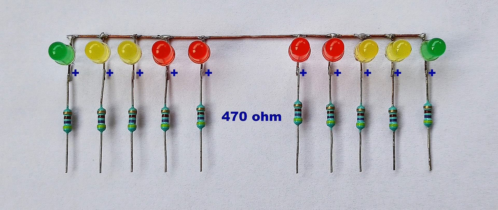
We solder 470 Ohm current limiting resistors to the pluses.
Next, diodes are soldered to the terminals of the resistors. Pay attention to the correct wiring of their poles. We took 1N4007 diodes. But instead of them, you can use any silicon ones with a permissible forward current of 0.3 A. The voltage drop across each of them will be about 0.7 V. This is what will create the effect of sequential ignition of the line LEDs depending on the signal level.
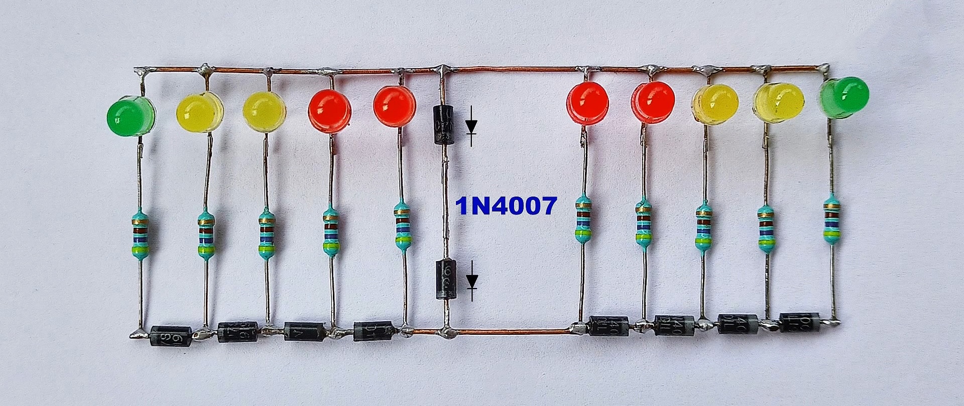
The assembly is completed by a pair of 470uF 25V electrolytic capacitors soldered in series and a pair of diodes. They form a voltage doubler. It is needed to rectify and double the input voltage. That's all, the diagram is ready.
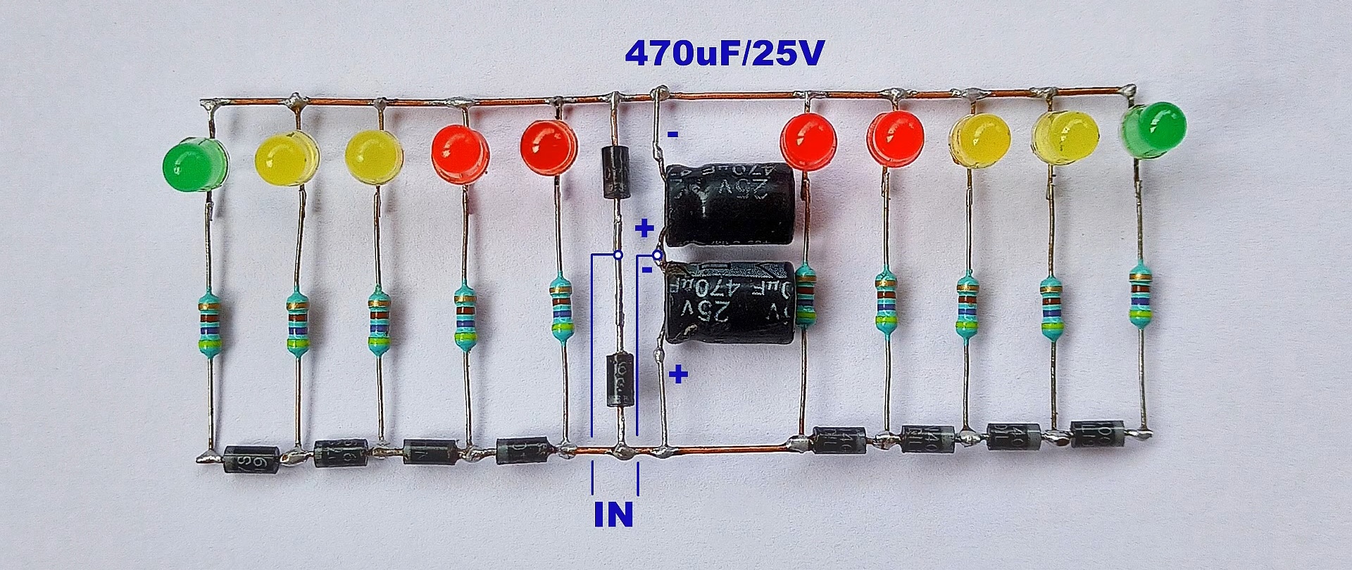
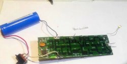
The voltage to the indicator is supplied directly from the speaker of the sound-reproducing device.
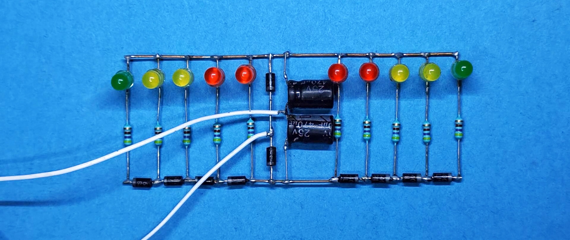
Turn it on. Everything is working!
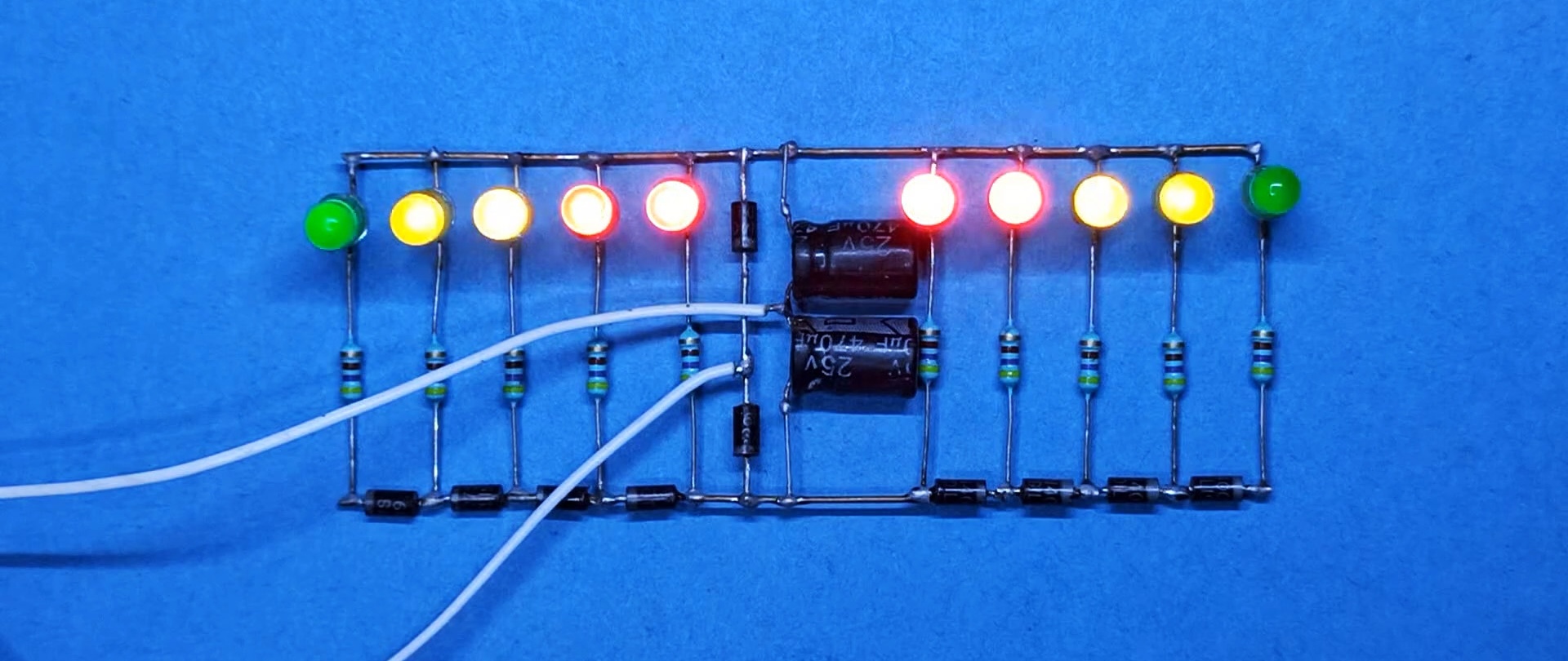
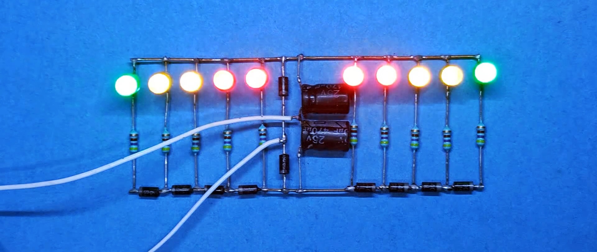
Please note that the volume of sound playback directly affects the number and brightness of lights. LEDs. The louder it is, the brighter the LEDs light up.