Do it yourself
Life hacks, master classes, useful tips, recipes.
home » Electronics » Level indicator without transistors, without microcircuits and without board
Level indicator without transistors, without microcircuits and without board

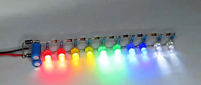
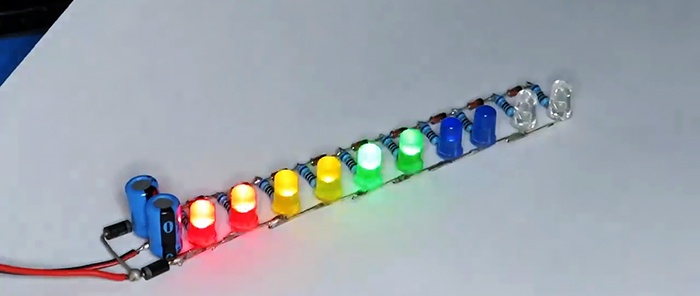
This is a very simple level indicator that is incredibly easy to make and does not contain transistors or microcircuits. It was assembled in 10 minutes using hinged mounting and works great.
The device connects directly to the speaker and displays the sound level. Can easily be used as a light and music decoration for any speaker or subwoofer.

Will need


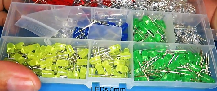
  • LEDs -
    Level indicator without transistors, without microcircuits and without board

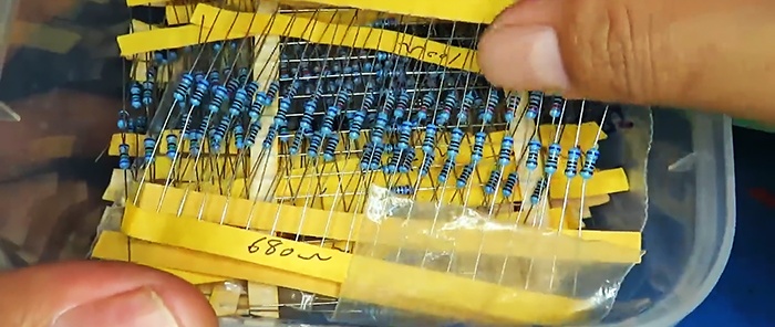
  • Resistors 680 Ohm -
    Level indicator without transistors, without microcircuits and without board

  • Diode 1N4007 -
    Level indicator without transistors, without microcircuits and without board

  • Zener diode 20 V -
    Level indicator without transistors, without microcircuits and without board

  • Capacitors 100 µF 25 V -
    Level indicator without transistors, without microcircuits and without board


Making a level indicator


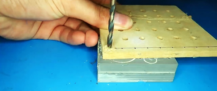
We will make a simple template from a piece of wooden backing. To do this, mark it along the line into uniform segments, drill holes for LEDs.
Level indicator without transistors, without microcircuits and without board

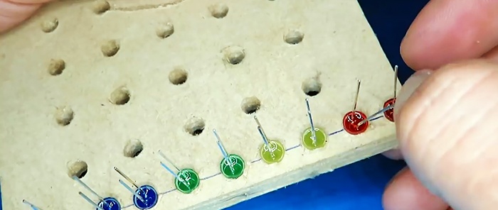
We insert LEDs so that their negative terminal is all on the same side.
Level indicator without transistors, without microcircuits and without board

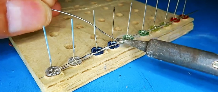
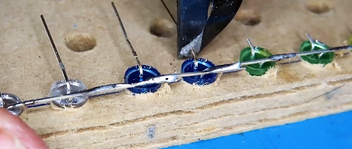
We bend the negative terminal with the adjacent LED and solder all the contacts into a line.
Level indicator without transistors, without microcircuits and without board

We bend the positive contact and cut it to a minimum.
Level indicator without transistors, without microcircuits and without board

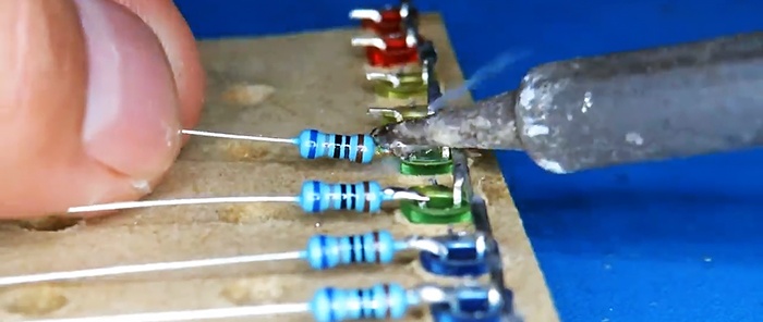
We take resistors and cut off the contacts on one side. Solder to the LEDs in order.
Level indicator without transistors, without microcircuits and without board

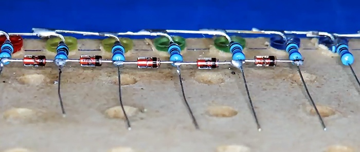
Next, we take the zener diodes, trim their leads and solder them. Pay attention to the position of the cathode and anode.
Level indicator without transistors, without microcircuits and without board

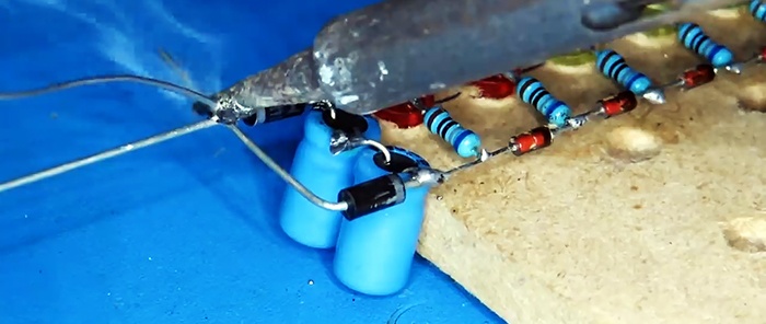
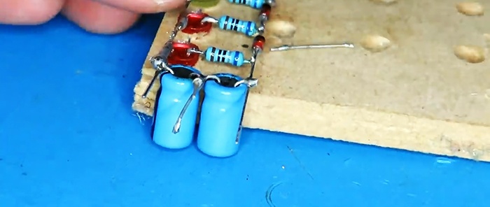
At the beginning we include two capacitors connected in series.
Level indicator without transistors, without microcircuits and without board

Solder the diodes.
Level indicator without transistors, without microcircuits and without board

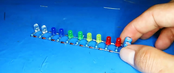
The indicator is ready for use.
Level indicator without transistors, without microcircuits and without board

Level indicator without transistors, without microcircuits and without board

We solder the wires to a bunch of diodes, and then to a bunch of capacitors.
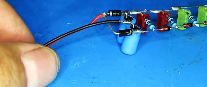
Level indicator without transistors, without microcircuits and without board

The indicator is connected directly to the dynamic head.
Level indicator without transistors, without microcircuits and without board

And it works great.
Level indicator without transistors, without microcircuits and without board

Level indicator without transistors, without microcircuits and without board

Principle of operation


A voltage doubler is built using diodes and capacitors to rectify and double the input voltage. Next, everything goes to the line with LEDs, a kind of ladder, where the steps are zener diodes, adding to each switching level LED + 0.6 V. Yes, although zener diodes are designed for a stabilization voltage of 20 V, they are turned on in the reverse way and work like diodes with a high reverse voltage. It is quite possible to replace them with 2 ordinary diodes connected in series, but then more of them would be needed.
As a result, during operation, each voltage value at the input “reaches” its LED.

Watch the video


In the video clip you can clearly see the operation of the indicator.
come back
Comment
  • bowtiesmilelaughingblushsmileyrelaxed relaxedsmirk
    heart_eyeskissing_heartkissing_closed_eyesflushedrelievedsatisfiedgrin
    winkstuck_out_tongue_winking_eyestuck_out_tongue_closed_eyesgrinningkissingstuck_out_tonguesleeping
    worriedfrowninganguishedopen_mouthgrimacingconfusedhushed
    expressionlessunamusedsweat_smilesweatdisappointed_relievedwearypassive
    disappointedconfoundedfearfulcold_sweatperseverecrysob
    joyastonishedscreamtired_faceangryragetriumph
    sleepyyummasksunglassesdizzy_faceimpsmiling_imp
    neutral_faceno_mouthinnocent
5+two=
Comments (16)
  1. Val Cioc
    #1 Val Cioc Guests 17 February 2020 20:48
    1
    Was it difficult to lay out the schematic diagram? With a ruler it’s clear, but with a doubler it’s not.
    1. Well
      #2 Well Guests 18 February 2020 14:00
      4
      Hold
  2. Walery
    #3 Walery Guests 17 February 2020 22:49
    8
    Level of what? I thought it was the water level.I looked through it with interest and what did I see at the end? Nothing and nothing...
    1. bbbt
      #4 bbbt Guests 20 February 2022 17:38
      2
      Well, not everyone is as brainless as you. Look how many people became interested and repeated, you can only please one. wipe your snot and go play with your lego.
  3. Guest Vasily
    #5 Guest Vasily Guests 18 February 2020 05:17
    2
    You definitely need to post a diagram. Even on a simple device.
  4. Lucik20
    #6 Lucik20 Guests 18 February 2020 12:59
    0
    Dear what voltage? LEDs ?
  5. G.B.
    #7 G.B. Guests 18 February 2020 15:03
    0
    Where is the world heading......It's faster to install it on a fiberglass board. Mark holes, drill and make paths - 10 minutes. Save your time.
  6. Guest Vladimir
    #8 Guest Vladimir Guests 18 February 2020 18:47
    1
    There will be no clear boundary. If you want to make a more complex circuit, order it from Ali.
  7. Guest Vladimir
    #9 Guest Vladimir Guests 19 February 2020 12:50
    3
    So in the 90s-2000s, Chinese portable farts came and all this blinked in them
  8. Sergey
    #10 Sergey Guests 27 February 2020 23:57
    0
    Thanks to the author! Repeated for 10 LEDs. I used old red ones LEDs. Resistance 470 ohms. I installed zener diodes or diodes that I found - also glass, with white stripes, I didn’t even bother. Everything works great, the dynamics are good. I used “Electronics E 20” in the amplifier, if anyone remembers such an old radio designer. The main thing is that everything is simple, accessible, without any microcircuits and transistors. It couldn't be simpler! Respect to the author!
  9. Alexander
    #11 Alexander Guests February 29, 2020 00:38
    2
    Thanks for the circuit diagram, I’ll remake mine, and I’ll also throw in an idea - from the last diode I can power the electronic key on the rack (protection against overload of the acoustics). The nice thing is that it can be mounted into the acoustics itself.Actually, I'll do this tomorrow.
    1. Sergey
      #12 Sergey Guests 29 February 2020 12:57
      0
      Good idea about protection! You will just need to introduce a delay of a second or two for the protection to operate, so that it does not react to peak signals. If you do, please share - interesting!
  10. Sergey
    #13 Sergey Guests 29 February 2020 22:35
    0
    I had to experimentally select a resistance (it turned out to be 18 ohms) and place it at the input in front of the electrolytes, because the entire indicator line lit up at approximately half the sound power of the speakers. And just at this moment there was a kind of stuttering of sound. The range of lighting has of course shifted towards louder sound, but now I’m happy with everything.

New Year's tree toy made from postcards | Do it yourself

Super fast chips in the microwave

How to decorate a sweater with lace | Do it yourself

Secret hiding place in a book | Do it yourself

«Do it yourself - with your own hands» - a site of interesting homemade products made from scrap materials and items at home. Step-by-step master classes with photos and descriptions, technologies, life hacks - everything a real master or just a craftsman needs for needlework. Crafts of any complexity, a large selection of directions and ideas for creativity.

We recommend reading

Washing machine error codes