Indicator circuit
The operation of the device is based on the initial switch-on voltage LED. Any Light-emitting diode - this is a semiconductor device that has a voltage limit point, only exceeding which it begins to work (shine). Unlike an incandescent lamp, which has almost linear current-voltage characteristics, the LED is very close to the characteristics of a zener diode, with a sharp slope of the current as the voltage increases.
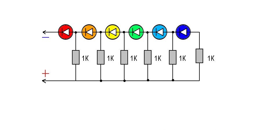
If you enable LEDs in a circuit in series with resistors, then each Light-emitting diode will begin to turn on only after the voltage exceeds the sum of the LEDs in the circuit for each section of the circuit separately.
The voltage threshold for opening or starting to light an LED can range from 1.8 V to 2.6 V. It all depends on the specific brand.
As a result, each LED lights up only after the previous one lights up.
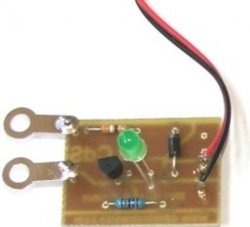
Assembling the battery charge level indicator

I assembled the circuit on a universal circuit board, soldering the outputs of the elements together. For better perception, I took LEDs of different colors.
Such an indicator can be made not only with six LEDs, but, for example, with four.
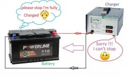
The indicator can be used not only for the battery, but to create a level indication on music speakers. By connecting the device to the output of the power amplifier, parallel to the speaker. This way you can monitor critical levels for the speaker system.
It is possible to find other applications of this truly very simple circuit.