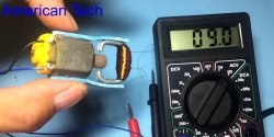
It is not at all necessary to measure the parameters of an electrical circuit with a tester; in many cases it is more convenient to use a universal probe that indicates the presence of these parameters through light signals. This is quite enough for convenient and safe work with electrical circuits.
The probe-indicator circuit under consideration does not contain batteries. Instead of the energy typically used in battery probes, it uses the energy of a charged capacitor.
Functionality.
The probe allows you to monitor the presence of alternating and direct voltage in the range from 24 to 220 V, carry out continuity testing of an electrical circuit with a resistance of up to 60 kOhm and determine the polarity in DC circuits.
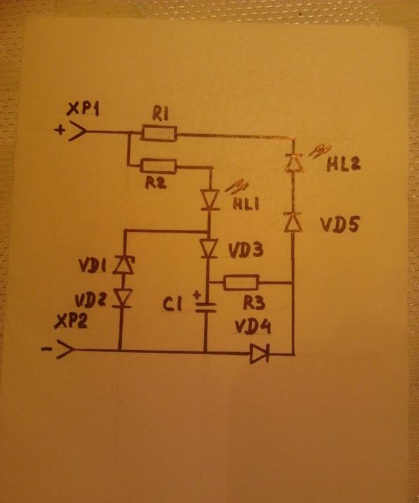
When probes XP1 and XP2 are connected to a DC source in accordance with the input polarity, green lights up Light-emitting diode HL1, indicating not only the presence of constant voltage in the controlled circuit, but also the presence of a plus at the point of contact of the XP1 probe.
Reversing the polarity on the probes causes the red light to light up. LED HL2, which, in addition to the presence of voltage, indicates contact with the plus of the HP2 probe.
When monitoring AC voltage, both light up at the same time. LED.
The continuity of the circuit during continuity is indicated by a red light. LED HL2.
This is the kind of information you can get with just two LEDs, built into this simple indicator probe.
Probe design.
Radio components. To sell the device, you must purchase or find in your supplies the following parts:
Resistors R1-220 kOhm and R2-20 kOhm, power 2W, R3-6.8 kOhm;
LEDs HL1 – AL 307G, HL2 – AL 307B;
Diodes KD2 – VD5 – KD103 (possible replacement for KD 102);
Zener diode VD1 – KS222ZH (possible replacement for KS220ZH, KS522A);
Capacitor C1 - K50-6 1000x25.
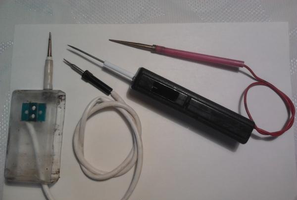
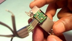
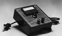
Frame. Particular attention should be paid to the choice of housing - the convenience of working with the probe depends on its configuration and dimensions. Let's consider two housing options. The first option uses a relay cover, the second uses the body of an unknown gadget.
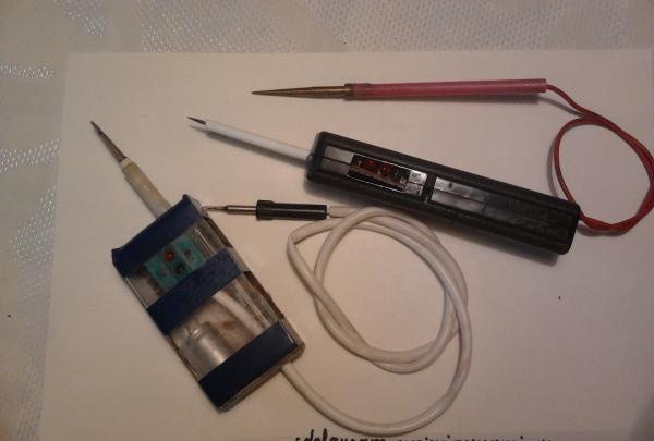
Holes are made in the housings for the output of the wire with the XP2 probe, LEDs are installed (only for the first option) and the XP1 probes are attached.
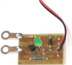
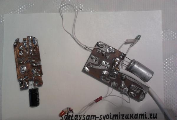
Pay. The dimensions of the case determine the geometry of the board. Installation can be hinged, but it is not difficult to do it on a printed circuit board. All radio components (except for LEDs in the first version) are mounted on a board that is mounted inside the case.
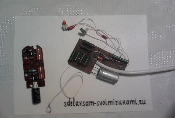
After installing the board into the case and soldering the conductors to the XP1 and XP2 probes, the probes and indicators are ready for use. The device does not need to be set up.
The charging time of the probe capacitor at a network voltage within 220-24V is 3-25 seconds. The capacitor discharge time when the probe probes are short-circuited is at least 2 minutes.