Not a single portable electronic device, be it a portable speaker for a phone, the phone itself, a player, etc. can't do without a battery. Lithium-ion batteries with a nominal voltage of 3.7 volts are now extremely popular; they are compact, relatively inexpensive and can have a large capacity. Their disadvantage is that they are afraid of deep discharge (below 3 volts), so when using them it is necessary to periodically monitor the voltage on the battery, otherwise it may simply break due to overdischarge. When creating homemade portable devices, it is often a good idea to install a module inside that shows what level the voltage is at the moment. The diagram of just such a module is presented below. Its main advantage is its versatility - the indication response limits can be adjusted within wide limits, so the circuit can be used both to indicate voltage on low-voltage lithium-ion batteries and on automobile ones.

Scheme
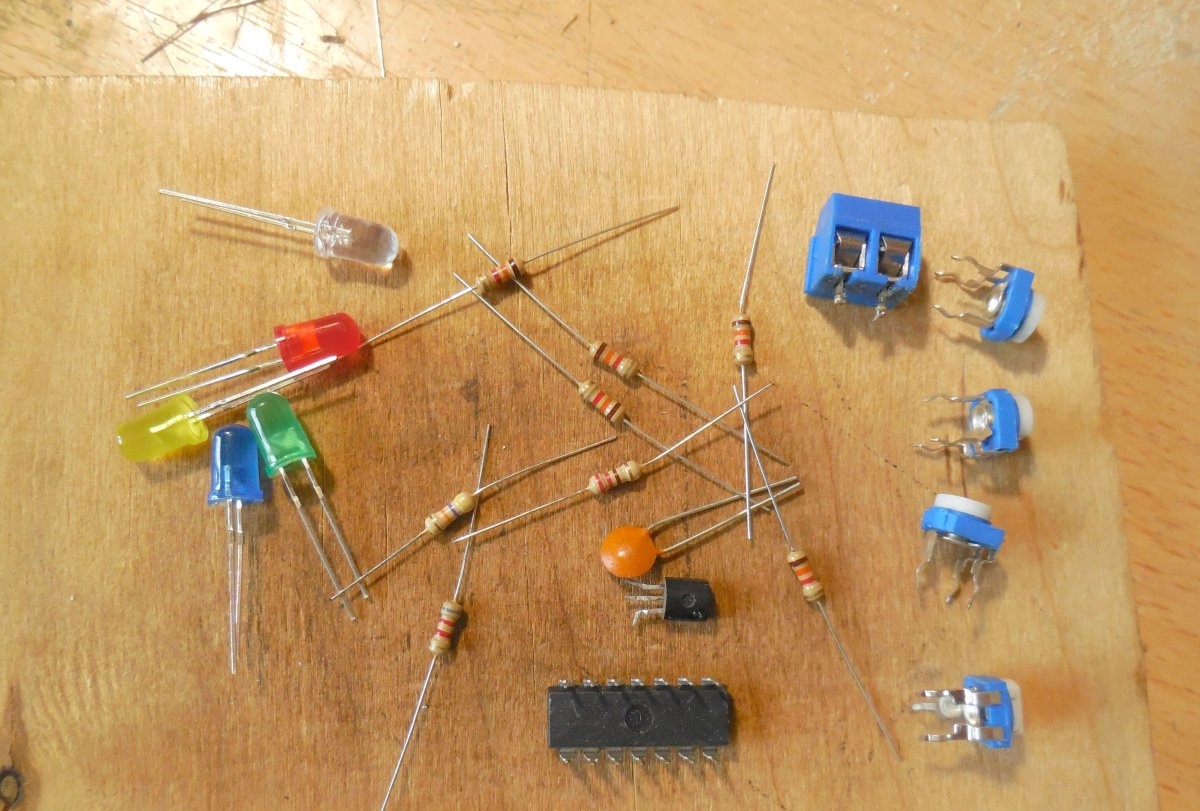
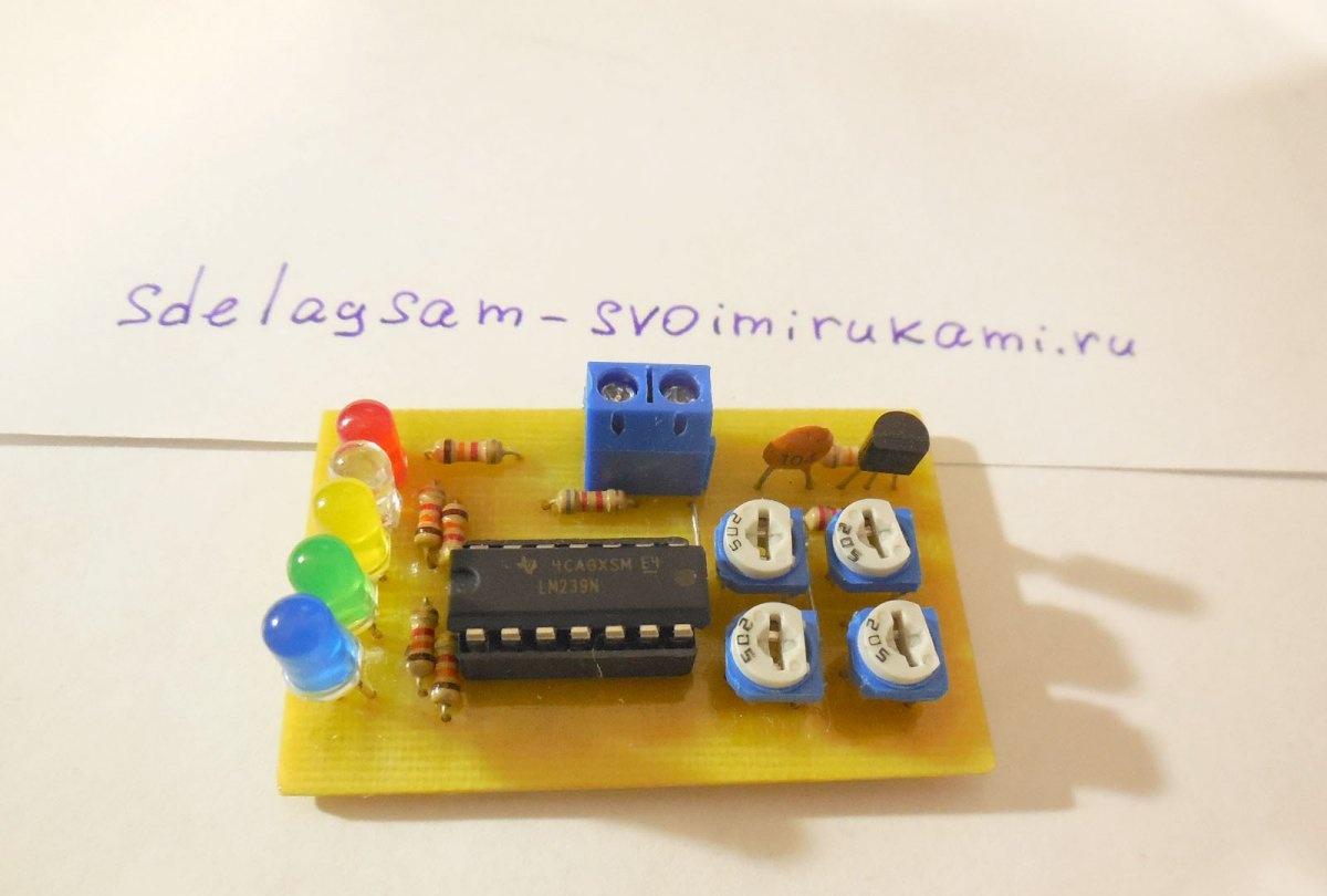
The circuit contains 5 LEDs, each of which lights up at a certain voltage on the battery. Operation threshold LEDs 1-4 is set by trimming resistors, and 5 Light-emitting diode lights up at the lowest voltage on the battery. Thus, if all 5 are lit LEDs, it means the battery is fully charged, and if only the first light is on, it means it’s time to charge the battery a long time ago. The circuit uses 4 comparators to compare the battery voltage with the reference voltage, all of them are contained in one LM239 chip package. To create a reference voltage of 1.25 volts, the LM317LZ chip is used. The divider of resistors R1 and R2 lowers the battery voltage to below 1.25 volts so that the comparators can compare it with the reference. Thus, if the circuit is to be used with a 12-volt car battery, the resistance of resistor R6 must be raised to 120-130 kOhm. LEDs To make the readings clearer, it is advisable to use different colors, for example, blue, green, yellow, white and red.
Indicator assembly
Download the board:
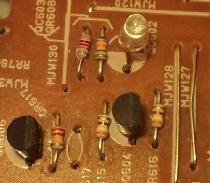
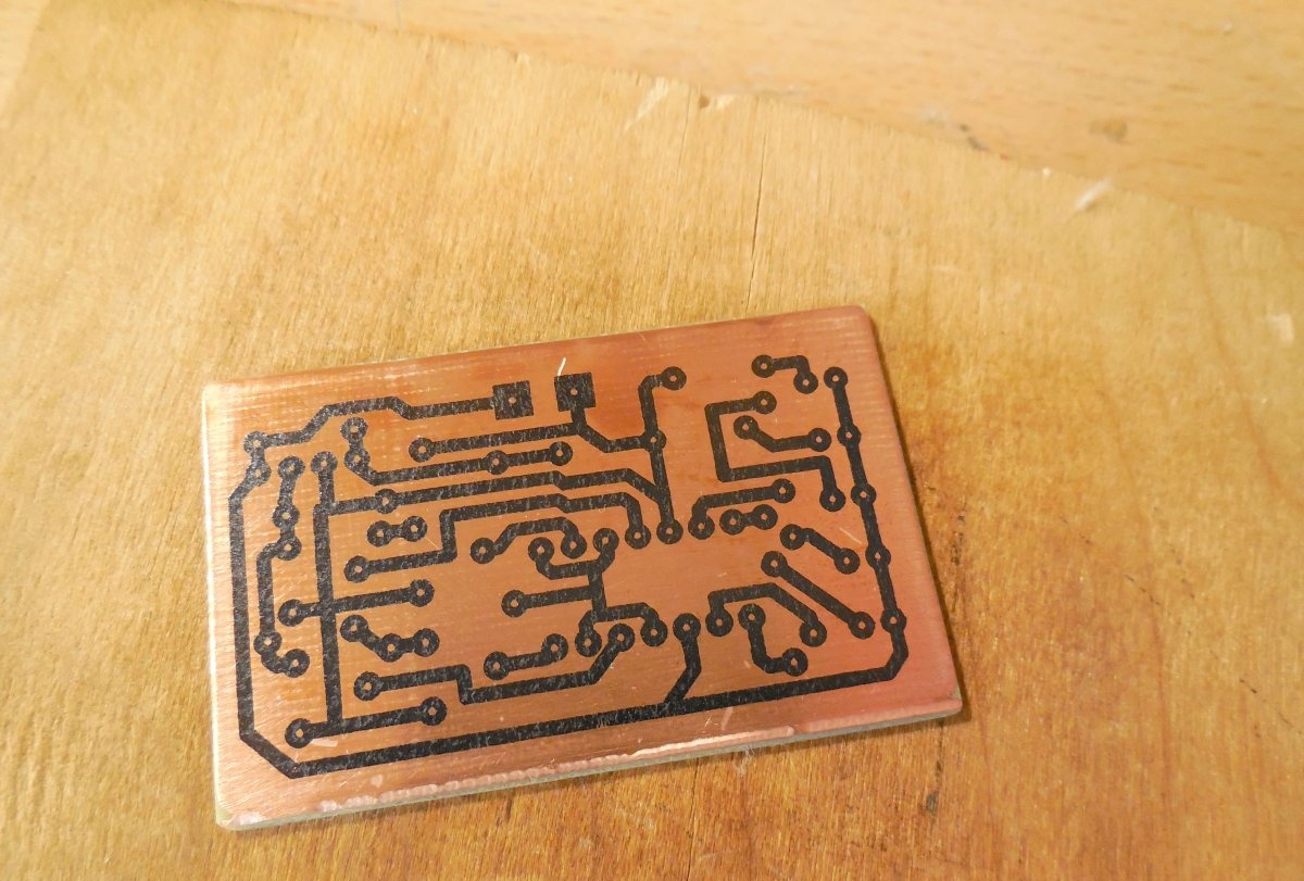
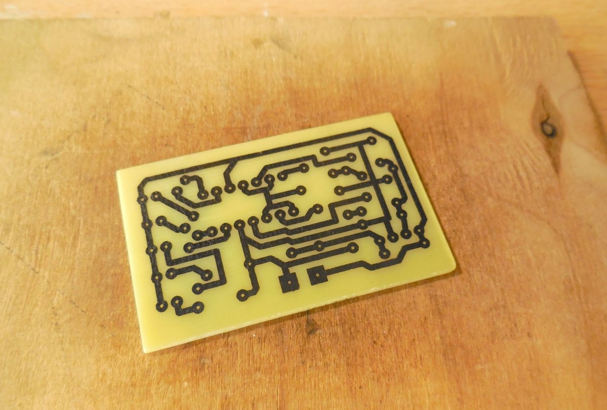
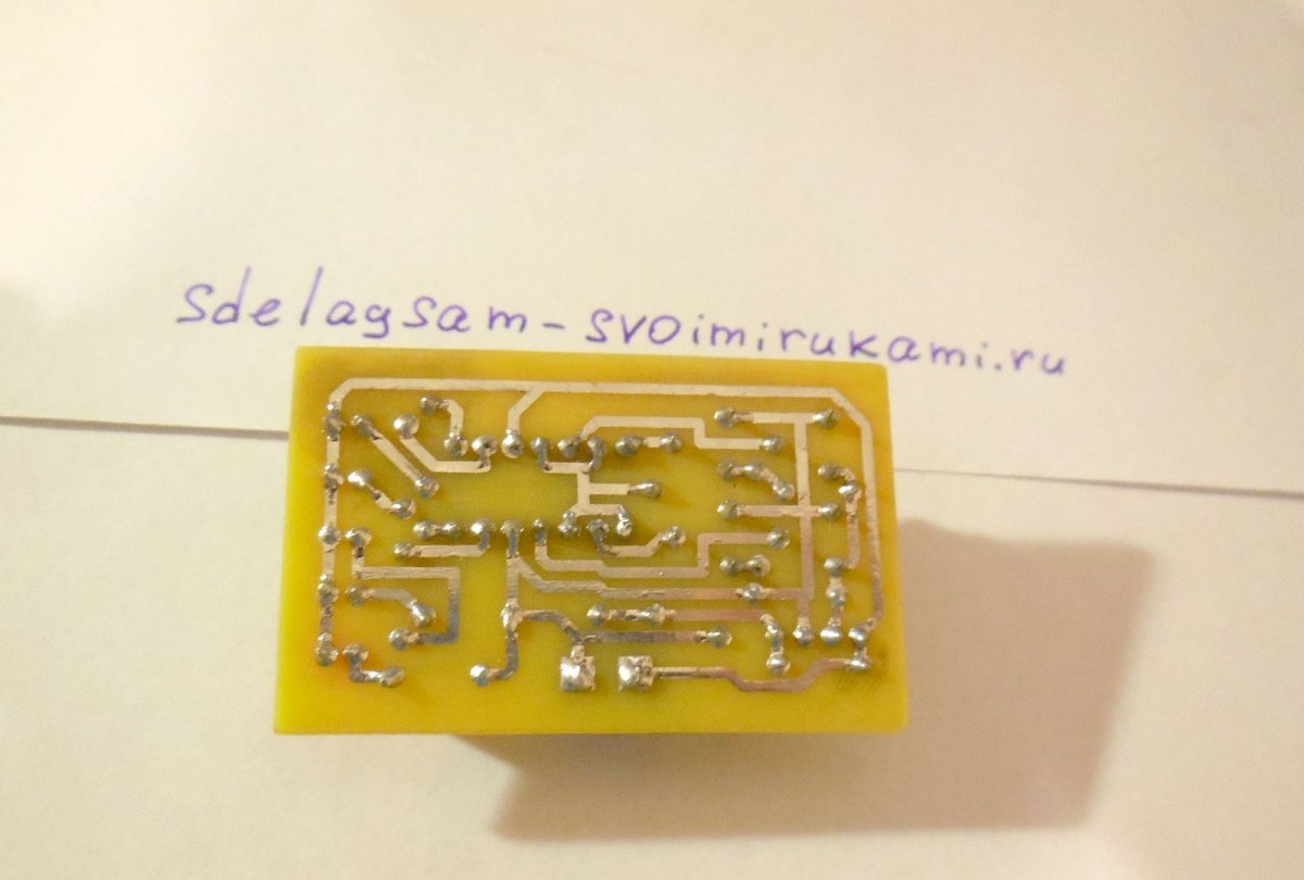
The entire circuit is manufactured on a printed circuit board measuring 35 x 55 mm. You can make it using the LUT method, which is what I did. A few photos of the process:
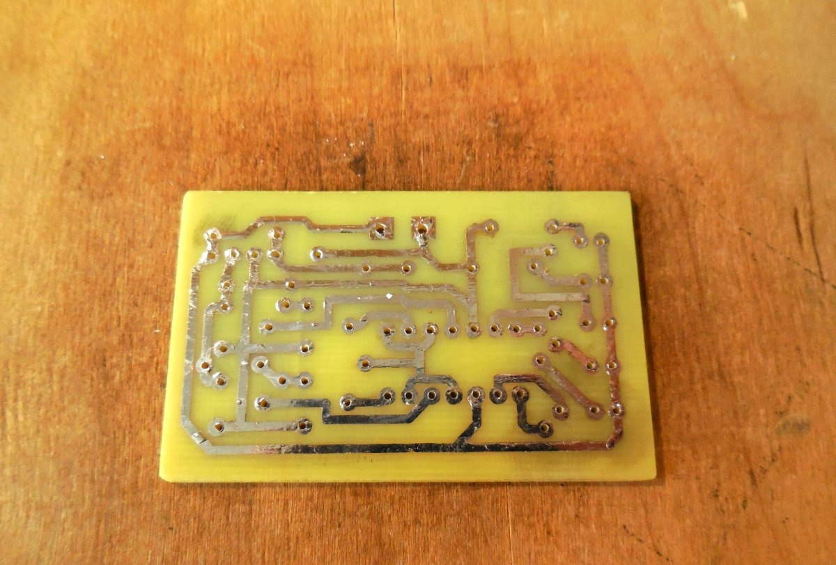
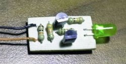
The holes are drilled with a 0.8 mm drill; after drilling, it is advisable to tin the paths. After making the board, you can begin installing parts on it - first of all, jumpers and resistors are installed, then everything else. LEDs can be removed from the board on wires, or they can be soldered in one row onto the board.To connect the wires to the battery, it is best to use a double screw terminal block, and it is advisable to install the microcircuit in a socket - then it can be replaced at any time. It is important not to confuse the pinout of the LM317LZ microcircuit; its first pin should be connected to the minus of the circuit, and the third to the plus. After completing the assembly, be sure to wash off any remaining flux from the board, check the correct installation, and test adjacent tracks for short circuits.
Testing and tuning
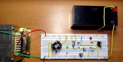
Now you can take any battery, connect it to the board and check the functionality of the circuit. First of all, after connecting the battery, we check the voltage at pin 2 of the LM317LZ, there should be 1.25 volts. Then we check the voltage at the connection point of resistors R1 and R2, there should be about 1 volt. Now you can take a voltmeter and an adjustable voltage source and, by rotating the trimming resistors, set the required response thresholds for each of the LEDs. For a lithium-ion battery, it would be optimal to set the following response thresholds: LED1 – 4.1 V, LED2 – 3.9 V, LED3 – 3.7 V, LED4 – 3.5 volts. When connecting the battery under test to the circuit, the polarity must be observed, otherwise the circuit may fail.
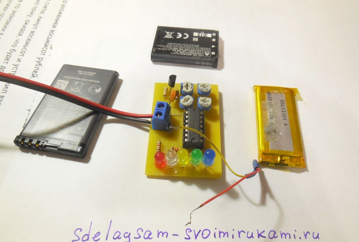
The video clearly demonstrates the operation of the indicator. When the first battery was connected, 4 LEDs lit up, which means the voltage on it was in the range of 3.7 - 3.9 volts, the second and third batteries lit up only three LEDs, which means the voltage on them was in the range of 3.5 - 3.7 volts.