Good afternoon, Dear Readers! Today we will talk about assembling a soldering station. So, let's go!
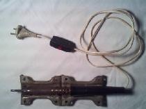
It all started when I came across this transformer:
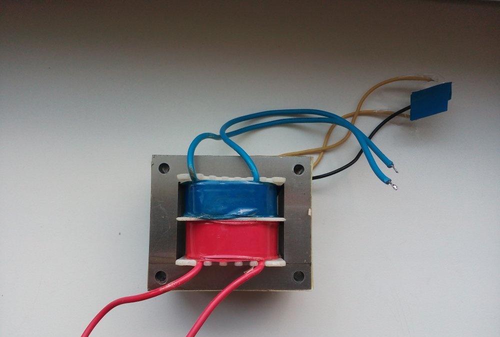
It is 26 Volt, 50 Watt.
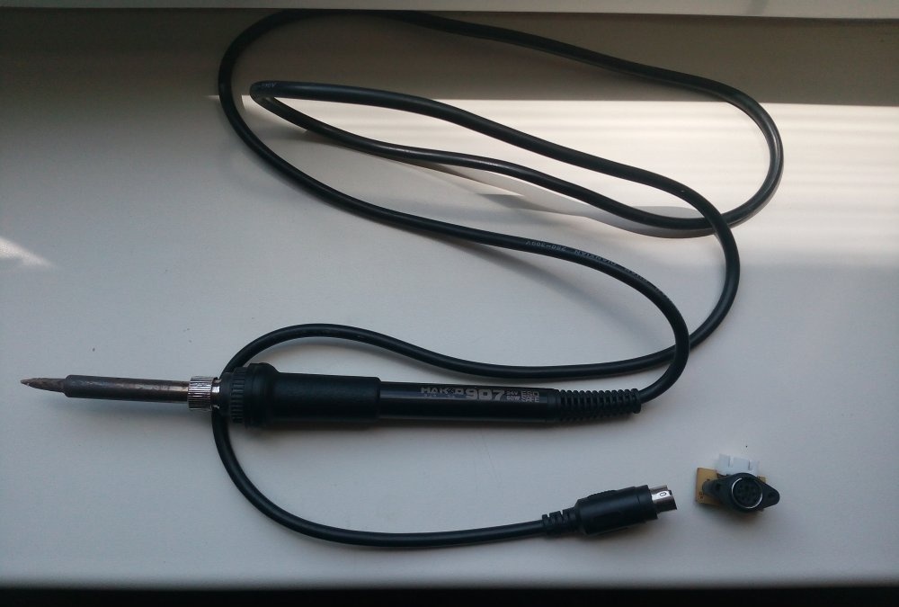
As soon as I saw it, a brilliant idea immediately came to my mind: to assemble a soldering station based on this transformer. I found this one on Ali soldering iron. According to the parameters, it is ideal - the operating voltage is 24 volts, and the current consumption is 2 amperes. I ordered it, a month later it arrived in shockproof packaging. In the picture, the tip is a little burnt, because I already connected the soldering iron to the transformer. I purchased the connector on the market, with a connector for four wires.
But connecting a soldering iron directly to a transformer is too simple, uninteresting, and the tip will deteriorate so quickly. Therefore, I immediately started thinking about the soldering iron temperature control unit.
First, I thought of an algorithm: the microcircuit will compare the value from the variable resistor with the value on the thermistor, and, based on this, it will either supply current all the time (heating the soldering iron), or supply it in “bundles” (holding the temperature), or not supply it at all (when the soldering iron is not used). The lm358 chip is perfect for these purposes - two operational amplifiers in one package.
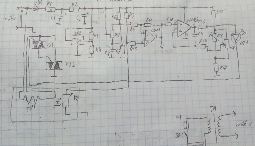
Soldering station regulator diagram
Well, let's move directly to the diagram itself:
Parts List:
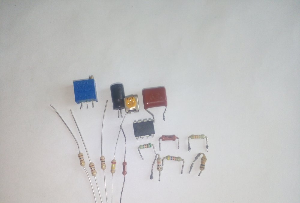
- DD1 – lm358;
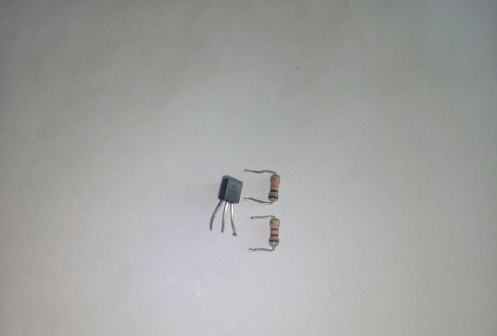
- DD2 – TL431;
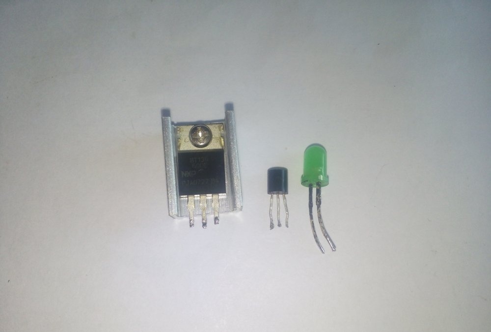
- VS1 – BT131-600;
- VS2 – BT136-600E;
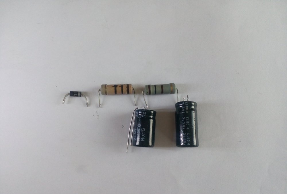
- VD1 – 1N4007;
- R1, R2, R9, R10, R13 – 100 Ohm;
- R3,R6,R8 – 10 kOhm;
- R4 – 5.1 kOhm;
- R5 – 500 kOhm (tuning, multi-turn);
- R7 – 510 Ohm;
- R11 – 4.7 kOhm;
- R12 – 51 kOhm;
- R14 – 240 kOhm;
- R15 – 33 kOhm;
- R16 – 2 kOhm (tuning);
- R17 – 1 kOhm;
- R18 – 100 kOhm (variable);
- C1, C2 – 1000uF 25v;
- C3 – 47uF 50v;
- C4 – 0.22uF;
- HL1 – green Light-emitting diode;
- F1, SA1 – 1A 250v.
Making a soldering station
At the input of the circuit there is a half-wave rectifier (VD1) and a current-quenching resistor.
Next, a voltage stabilization unit is assembled on DD2, R2, R3, R4, C2. This block reduces the voltage from 26 to 12 volts needed to power the microcircuit.
Then comes the control unit itself on the DD1 chip.
And the concluding block is the power part. From the output of the microcircuit through the indicator Light-emitting diode the signal goes to triac VS1, which controls the more powerful VS2.
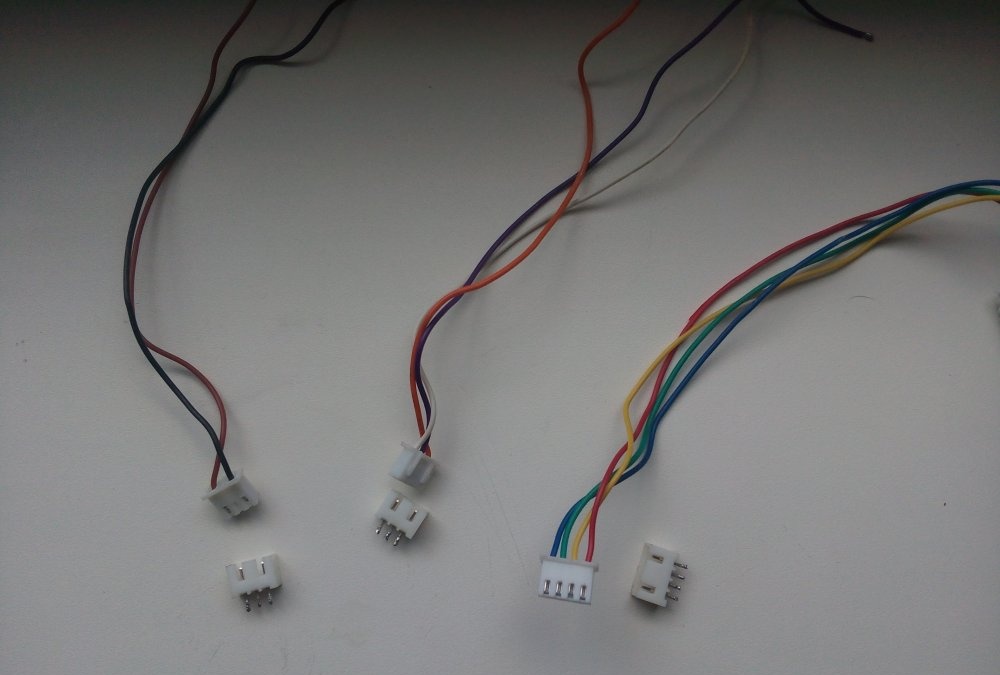
We also need several wires with connectors. This is not necessary (the wires can be soldered directly), but it’s just right for Feng Shui.
For the printed circuit board we need PCB measuring 6x3 cm.
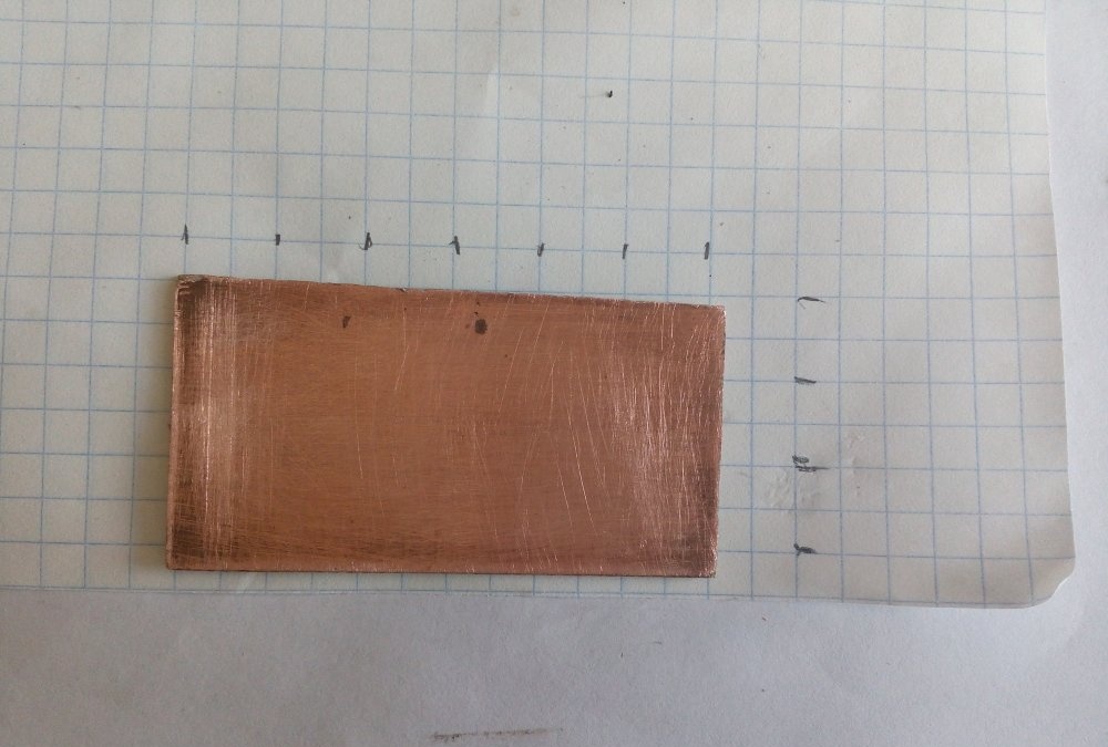
We transfer the design to the board using the laser-iron method.To do this, print this file and cut it out. If something is not transferred, we finish painting it with varnish.
Next, we throw the board into a solution of hydrogen peroxide and citric acid (ratio 3:1) + a pinch of table salt (it is a catalyst for a chemical reaction).
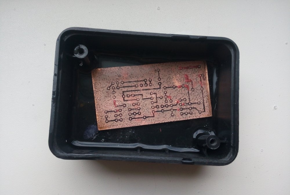
When the excess copper dissolves, take out the board and rinse with running water
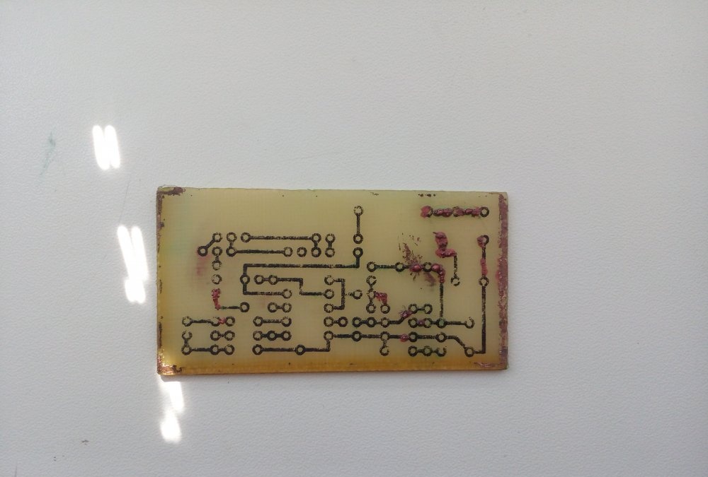
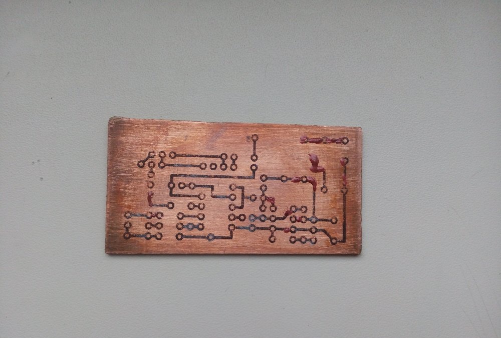
Then remove the toner and varnish with acetone, drill holes
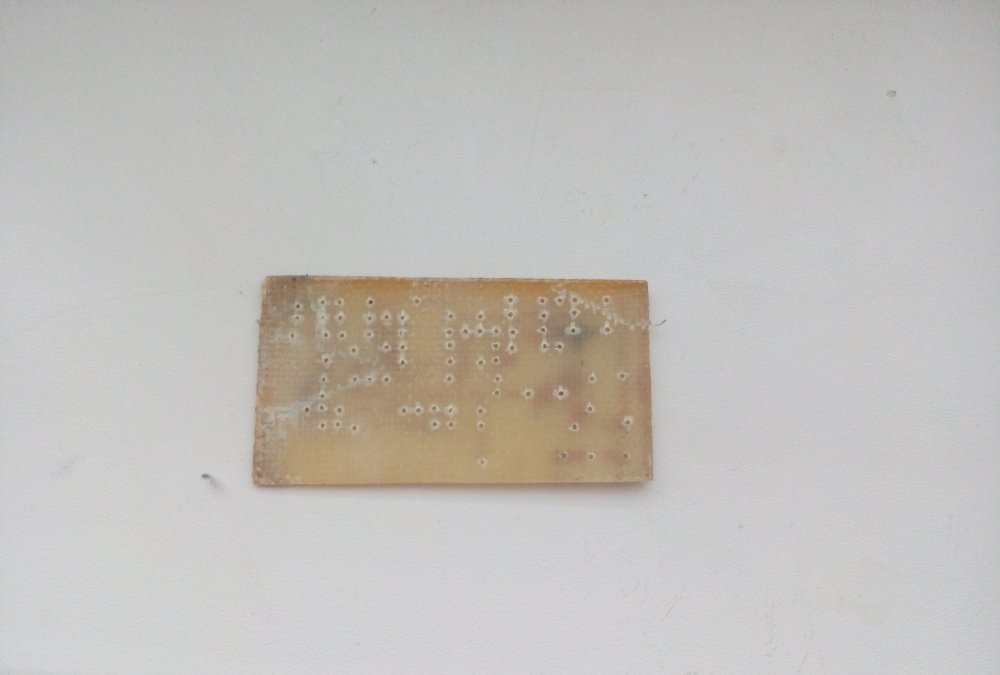
That's all! The printed circuit board is ready!
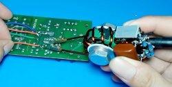
All that remains is to tin the tracks and solder the components correctly. Solder using this picture as a guide: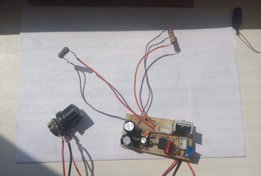

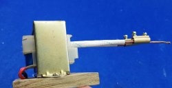
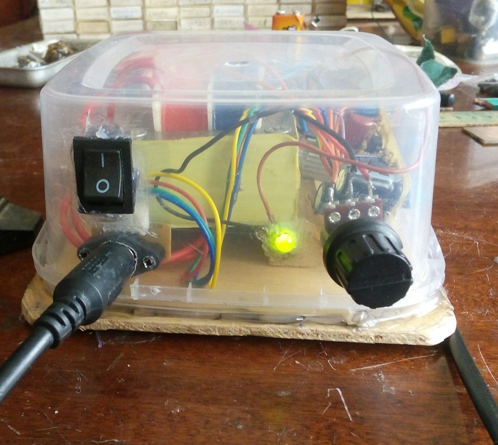
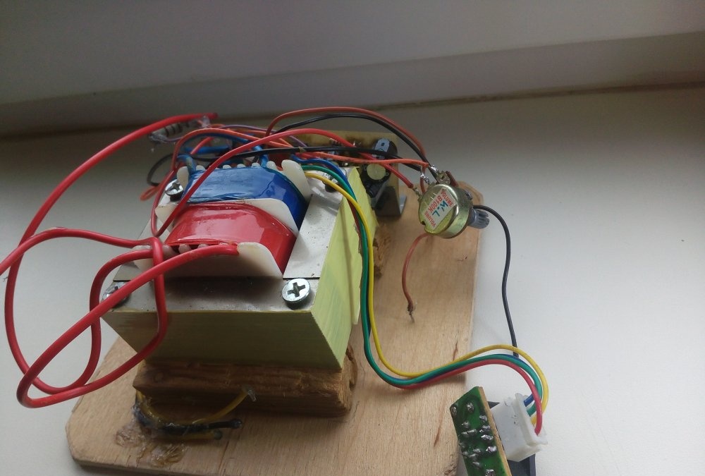
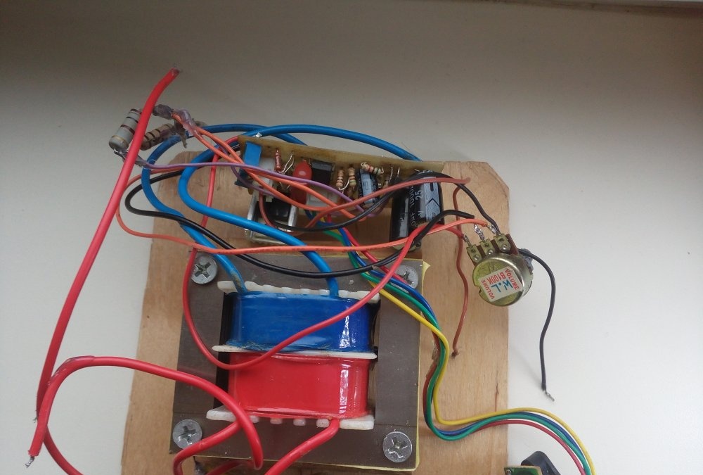
So, we collected the fee. Now we need to put all this into the case. The base will be a square of plywood measuring 12.6x12.6 cm.
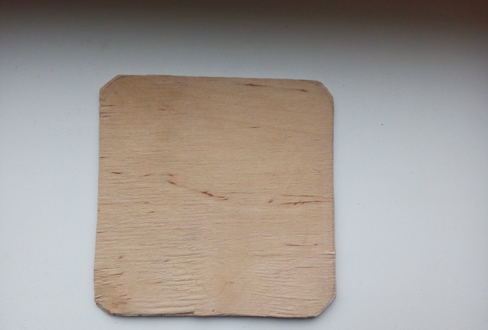
The transformer will be in the middle, fixed with screws on small wooden blocks, the board will “live” nearby, screwed to the base through a corner with a bolt.
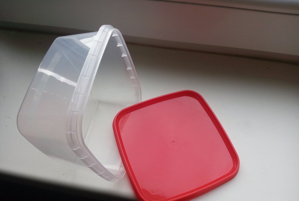
And the dome will be an ordinary tray purchased from a household. goods.
We make several holes on the front panel: for a switch, a variable resistor, Light-emitting diode and a connector for a soldering iron. On the back panel there is a hole for the power plug.
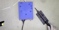
And this is what ended up happening:
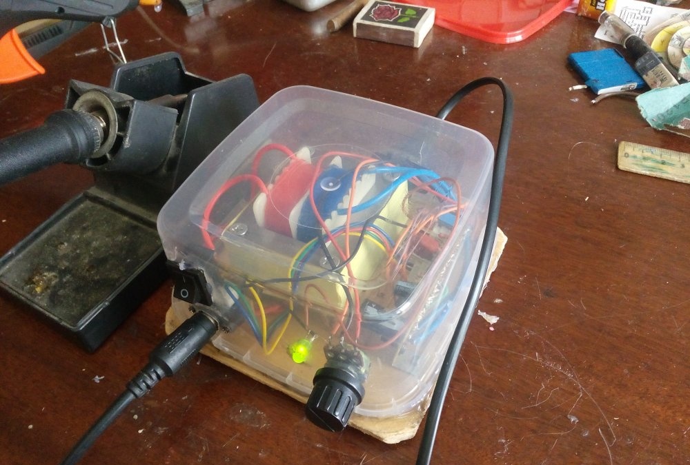
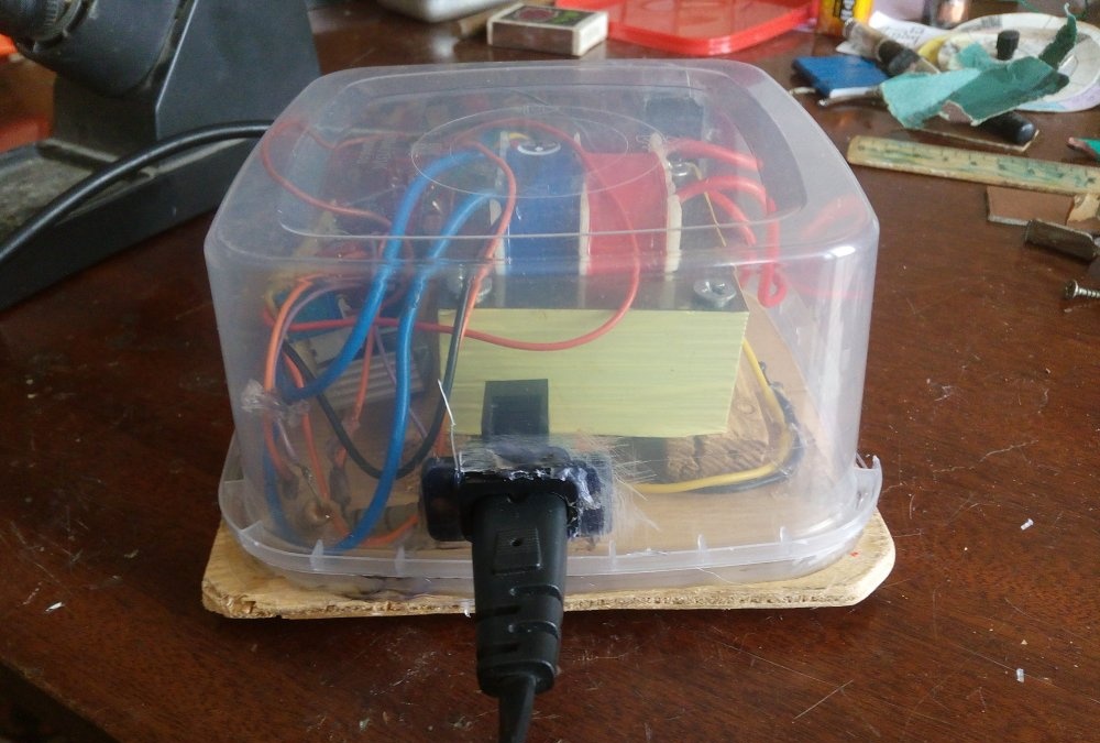
The circuit started the first time it was turned on and does not require adjustment.
This circuit can also be powered from 12V, which makes it universal. To do this, it is necessary to exclude DD2, R2, R3, R4 and C2 from the general circuit. Also, the thermistor in the circuit should be replaced with a fixed resistor with a nominal value of 100 Ohms.
This concludes my article. Good luck with your repetition everyone!
P.S. If the soldering iron does not start, check every connection on the board!