The simplest brightness control circuit LEDs, presented in this article, can be successfully used in car tuning, and simply to increase comfort in the car at night, for example, to illuminate the instrument panel, glove compartments, and so on. To assemble this product, you do not need technical knowledge, you just need to be careful and careful.
Voltage 12 volts is considered completely safe for people. If you use an LED strip in your work, then you can assume that you will not suffer from a fire, since the strip practically does not heat up and cannot catch fire from overheating. But accuracy in work is needed to avoid a short circuit in the mounted device and, as a result, a fire, and therefore to preserve your property.
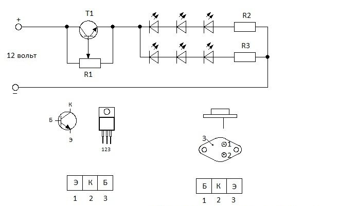
Transistor T1, depending on the brand, can adjust the brightness LEDs with a total power of up to 100 watts, provided that it is installed on a cooling radiator of the appropriate area.
The operation of transistor T1 can be compared with the operation of an ordinary water faucet, and potentiometer R1 with its handle. The more you unscrew, the more water flows. So it is here.The more you unscrew the potentiometer, the more current flows. If you tighten it, it leaks less and shines less. LEDs.
Regulator circuit
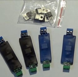
For this scheme we will not need many parts.
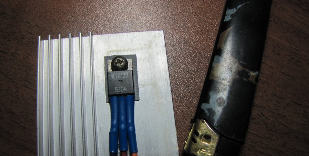
Transistor T1. You can use KT819 with any letter. KT729. 2N5490. 2N6129. 2N6288. 2SD1761. BD293. BD663. BD705. BD709. BD953. These transistors must be selected depending on the power LEDs you plan to regulate. Depending on the power of the transistor, its price also depends.
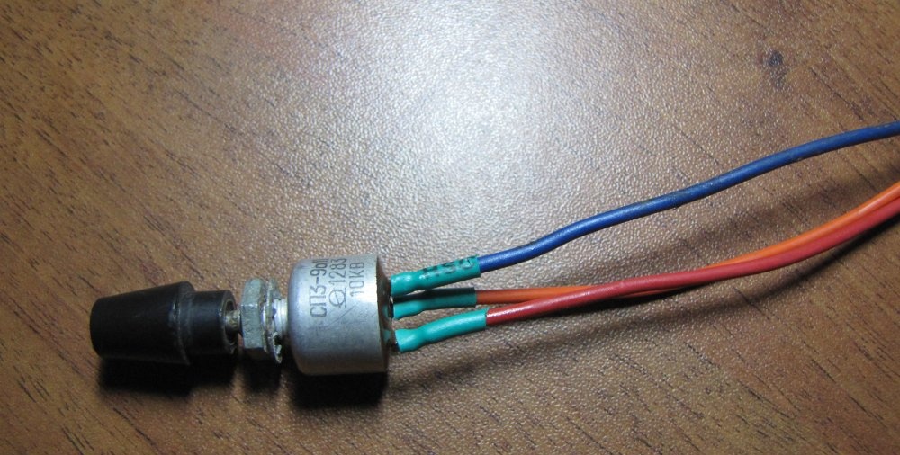
Potentiometer R1 can be of any type with a resistance from three to twenty kilo-ohms. A three-kilo-ohm potentiometer will only slightly reduce the brightness LEDs. Ten kilo-ohms will reduce it to almost zero. Twenty – will adjust from the middle of the scale. Choose what suits you best.
If you use an LED strip, then you won’t have to bother with calculating the damping resistance (in the diagram R2 and R3) using formulas, because these resistances are already built into the strip during manufacture and all you need to do is connect it to a voltage of 12 volts. You just need to buy a tape specifically for 12 volts. If you connect a tape, then exclude resistances R2 and R3.
They also produce LED assemblies designed for 12 volt power supply, and LED bulbs for cars. In all these devices, quenching resistors or power drivers are built in during manufacture and are directly connected to the on-board network of the machine. If you are just taking your first steps in electronics, then it is better to use just such devices.
So, we have decided on the components of the circuit, it’s time to start assembling.
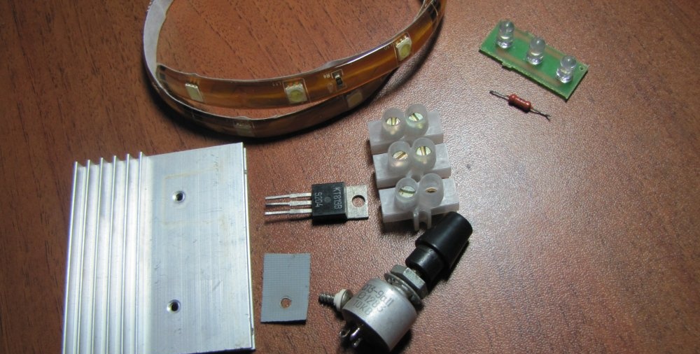
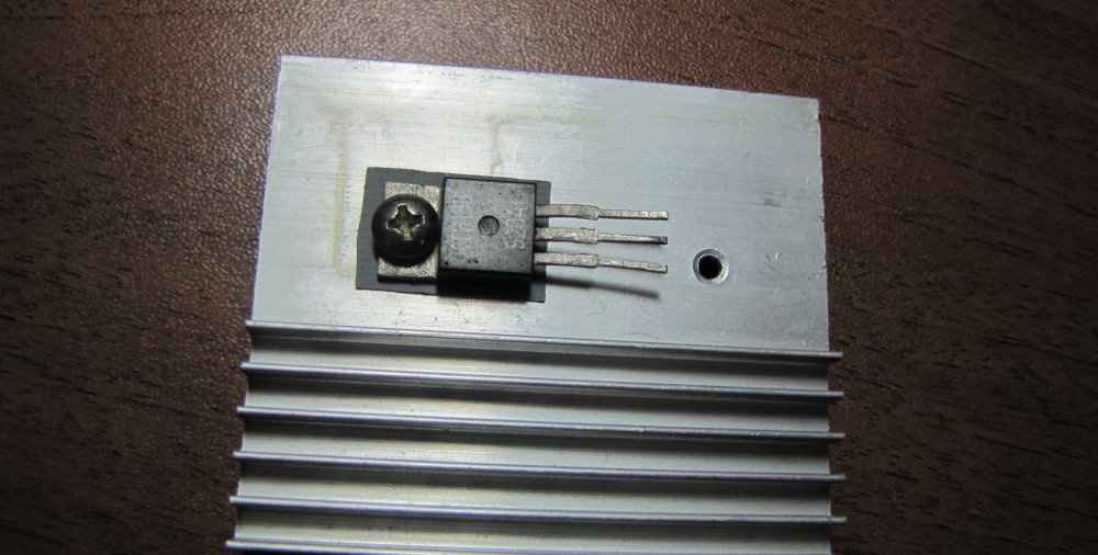
We screw the transistor onto a bolt to the cooling radiator through a heat-conducting insulating gasket (so that there is no electrical contact between the radiator and the vehicle's on-board network, in order to avoid a short circuit).
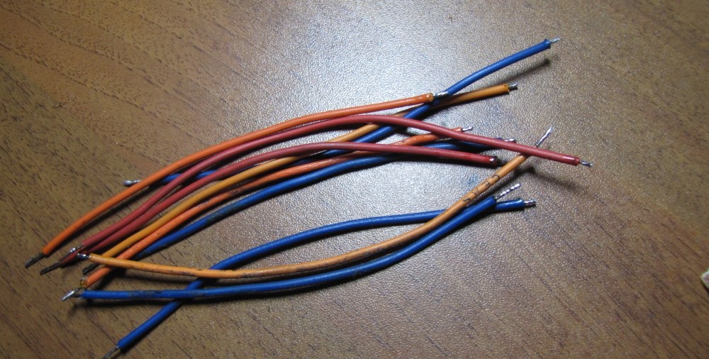
Cut the wire into pieces of the required length.
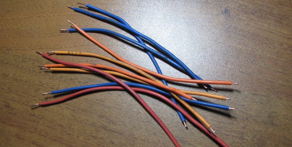
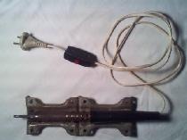
We strip the insulation and tin it with tin.
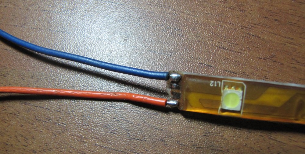
Clean the contacts of the LED strip.
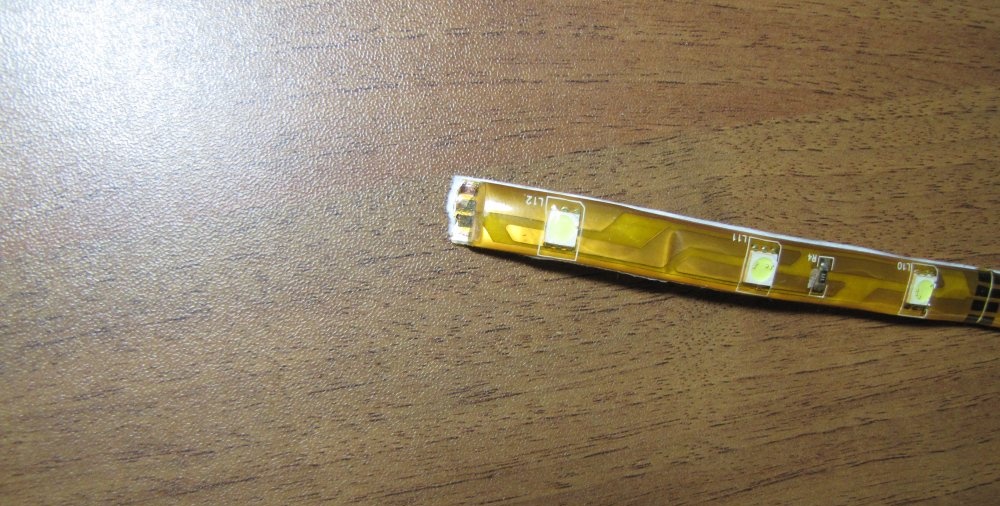
Solder the wires to the tape.
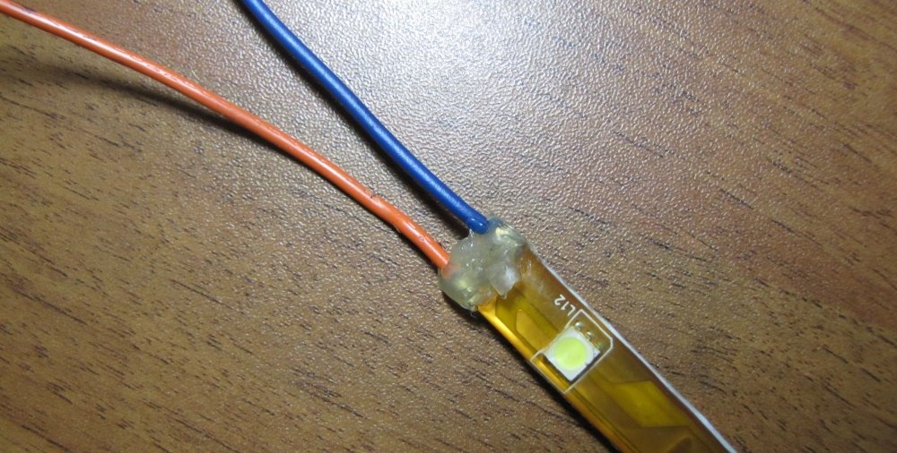
We protect the exposed contacts with a glue gun.
We solder the wires to the transistor and insulate them with heat shrink casing.
We solder the wires to the potentiometer and insulate them with heat-shrinkable casing.
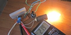
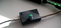
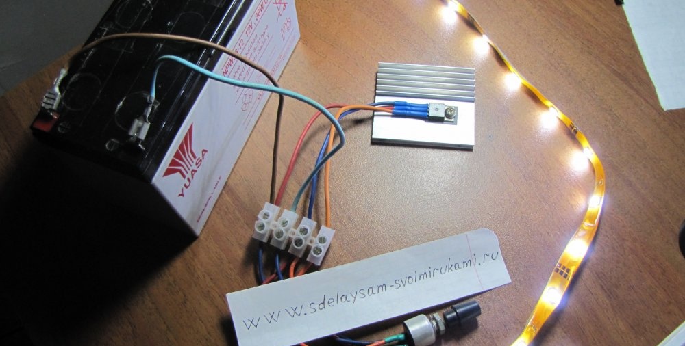
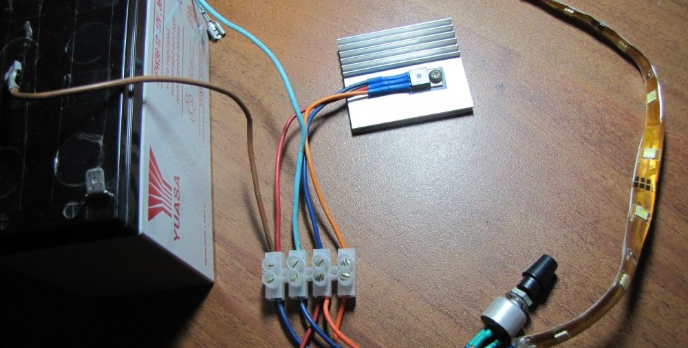
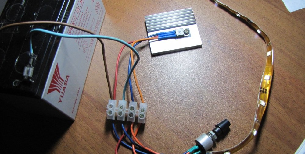
We assemble the circuit using a contact block.
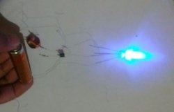
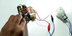
We connect it to the battery and test it in different modes.
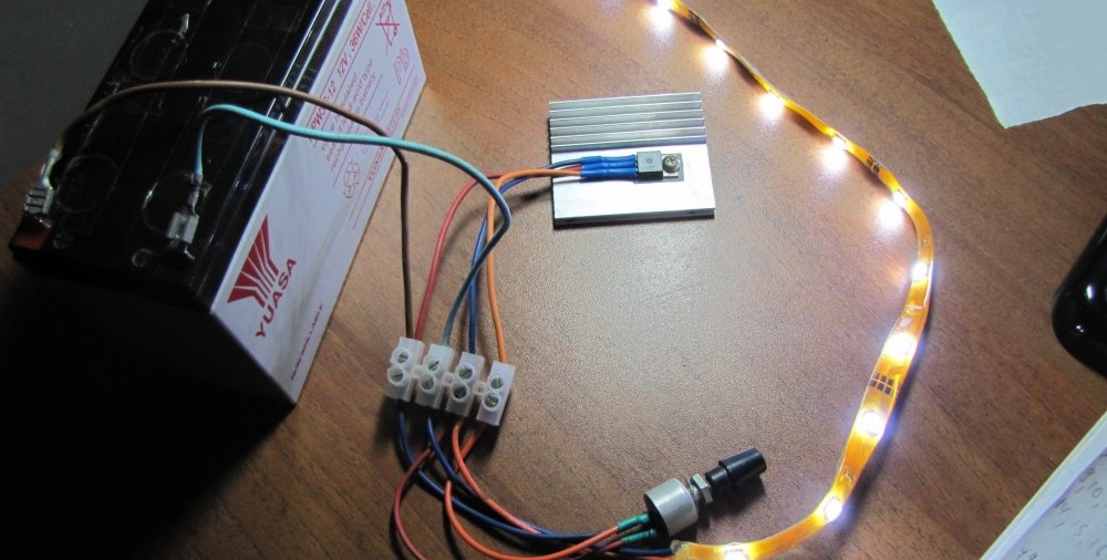
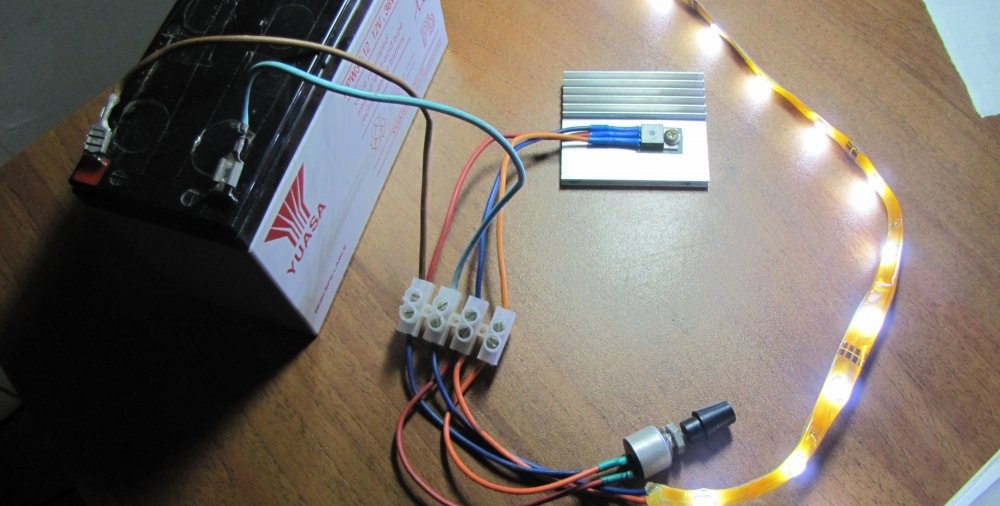
Everything works well.