It can be used in various devices for sound notification. For example, an alarm system, sound duplication of a turn signal in a car or bicycle, a low battery signal, and so on. You can, of course, take a ready-made beeper, for example, from an old Chinese alarm clock, musical card or other devices, but I decided to make it myself with my own hands. It's more interesting that way.
Another goal of the assembly is to popularize youth’s passion for radio electronics. If this site can captivate at least a few people with such an interesting and good cause, then its task can be considered completed.
I took a simple, but proven scheme. I don’t even remember where I got it from.
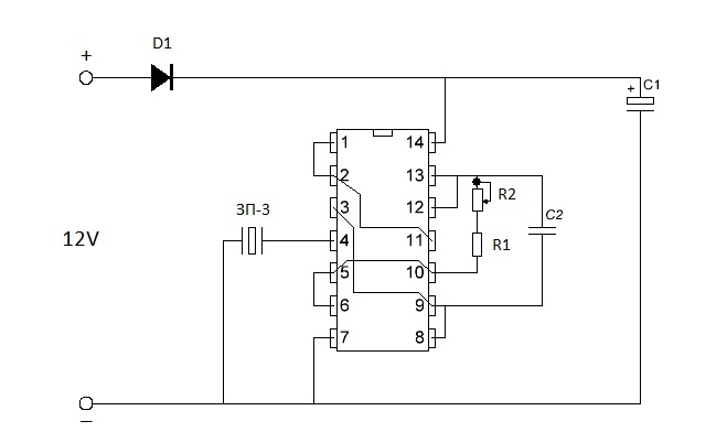
Piezo sound emitter circuit
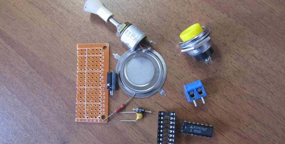
Parts for assembling the horn circuit
Parts for the circuit can be used in a very wide range.
For example, La7 microcircuits from the K176, K164, K564, K561 or K561LE5 series or imported analogues.In order not to solder and desolder the microcircuit, it is best to take a special contact pad and solder it into the circuit (it costs pennies), and replacing the microcircuit will take seconds, and during soldering there is no risk that the microcircuit will overheat or be damaged by static electricity. In addition, you can easily test different brands of microcircuits for performance.
Capacitor C1 is polar with a voltage of at least 15 volts and a capacity of 47 to 500 microfarads. If you want the buzzer to immediately stop after turning off the power, then this capacitor must be excluded, otherwise after turning off the power, the sound continues until the capacitor is discharged.
Ceramic capacitor C2 from 0.1 to 0.47 microfarads. They are designated by numbers on the cover - 104, 154, 224, 474.
Resistor R1 from 5 to 50 kilo Ohms. Any power, but less is better. So that the dimensions are not large.
Potentiometer R2 from 68 to 500 kilo Ohms. The power is the same, less.
You can use any diode you like. It is used to protect the chip from improper power connections. You can do without it altogether.
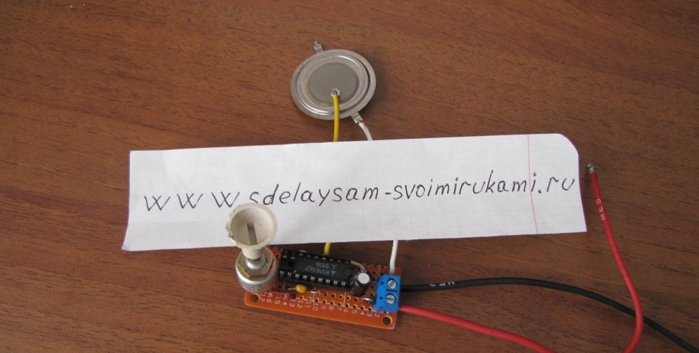
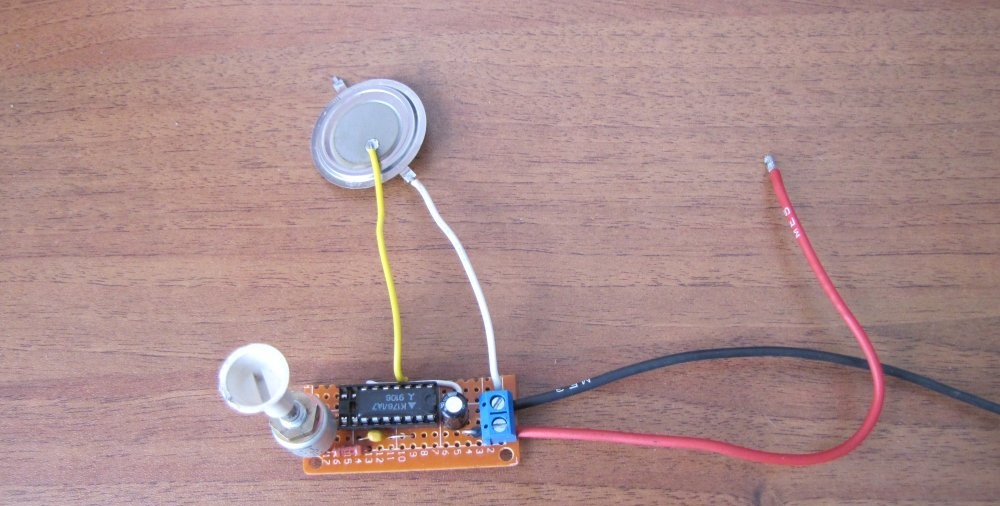
Sound emitter ZP-3 or any similar.
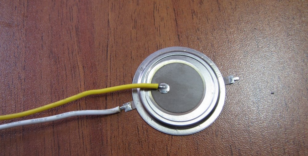
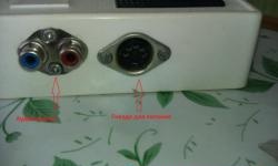
How to connect ZP-3? If the ZP-3 sound emitter is new, then you need to solder wires to it, as in the photo. Soldering is easy if you use flux. We solder one wire to the membrane. Solder the second wire to either of the two terminals.
The supply voltage of the circuit is 12 volts. This could be a battery, rectifier or any other DC source.
The sound tone of the device depends on the values of the circuit elements, so you can experiment by changing capacitors and resistors to achieve a sound that you like.
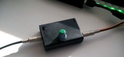
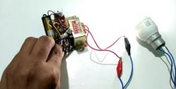
In order not to make a printed circuit board, it is best to take and use a breadboard; it turns out much easier and faster.
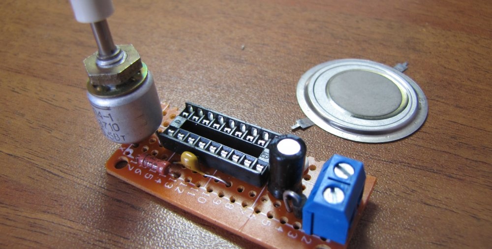
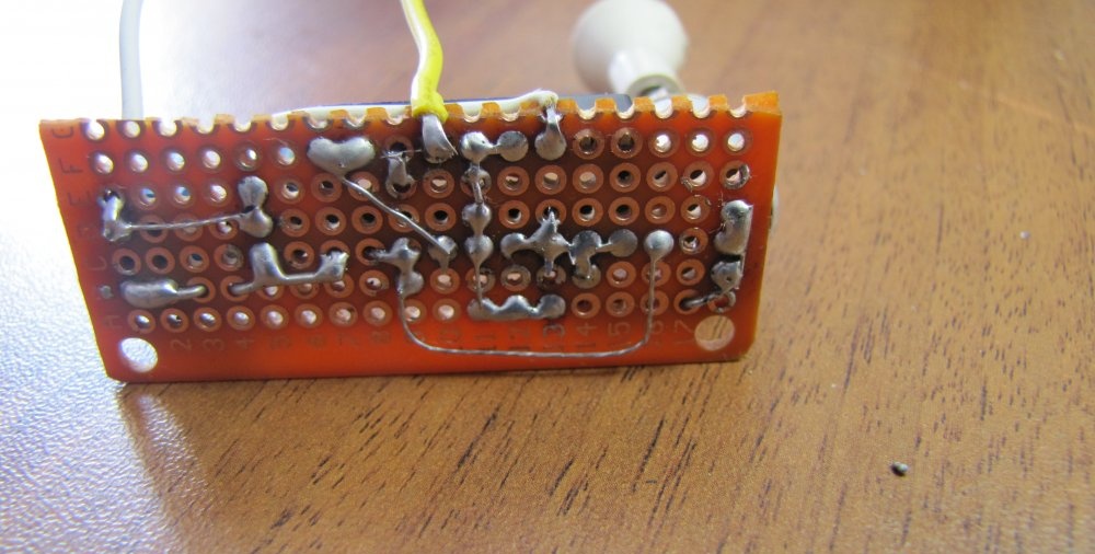
We place the parts more tightly on the breadboard, solder them, check them again and test the sound by connecting them to a power source.
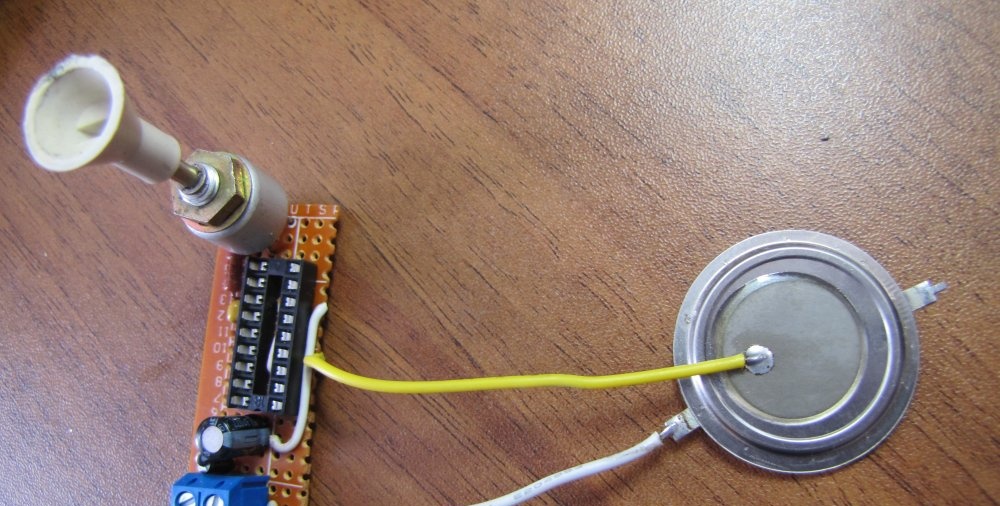
With proper assembly and serviceable parts, the circuit starts working immediately and does not require adjustment. If you don’t like the tone, then adjust the potentiometer to your taste.
The signaling device is assembled.