Do it yourself
Life hacks, master classes, useful tips, recipes.
home » Electronics » DIY amplifier » Amplifier on TDA7496SA
There were only schematics on these microcircuits on the Internet, but I couldn’t find the assembled amplifier. Operating mode AB, Supply voltage 10…32 Volts, Stereo configuration, Operating temperature 0…70 degrees. Such microcircuits can be found in modern televisions and, probably, at least someone managed to pull out such a thing. The output is 5+5 watt, load 8 ohms.

amplifier circuit

microcircuit pin layout


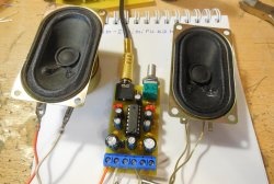
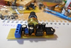
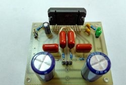
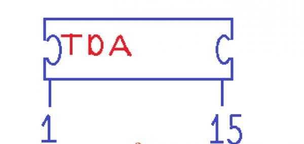
I didn’t have a printed circuit board for it and decided to assemble it on another board from a radio receiver, where there was a microcircuit that has 16 legs. And so, first we remove all the parts from the board, then carefully remove the microcircuit so that the tracks remain intact. We install the TDA7496SA (it has 15 legs) in the place where the micro from the receiver stood. You'll have to tinker a little, because the paths go in different directions. The microcircuit body must be connected to the minus.

assembled circuit


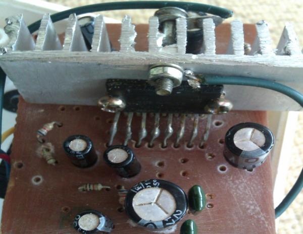
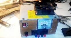
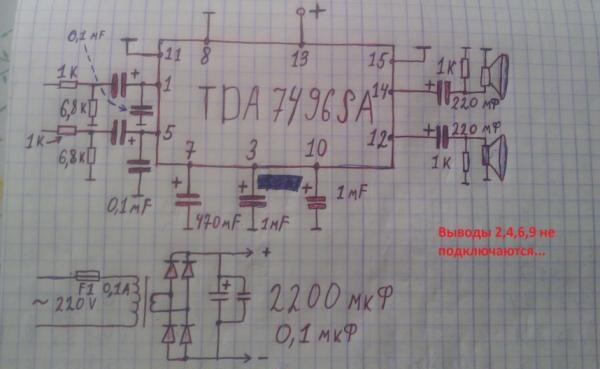
And of course you can’t leave it without a radiator, otherwise it will heat up very quickly and may fail. As for the transformer, I took it from an old power supply and the output is 21.22 volts and no less than 0.6 amperes. If the voltage is somehow below 16 volts, you will have to install 220 uF capacitors at the output, otherwise the sound quality will be worse than we thought.Follow the amp, the same is very important. If it is more than 22 volts, then you can replace it with 470 uF and 1000 uF and then there is no point.
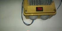
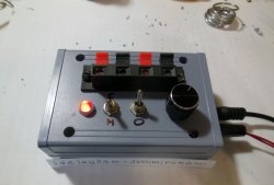
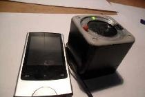
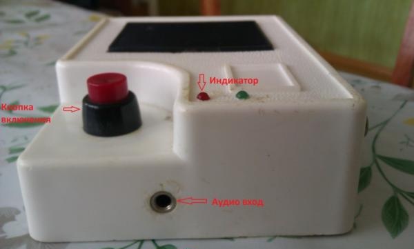
Here I have already placed the board in the housing from the old doorbell. The transformer did not fit and I decided to assemble it separately with a diode bridge. For the audio input, I installed a headphone jack and I think it cannot be replaced with anything, and the same is true in other devices. It has three terminals inside, one is a general minus, and the other two can be said to be pluses (this is for a stereo system).

indicator location


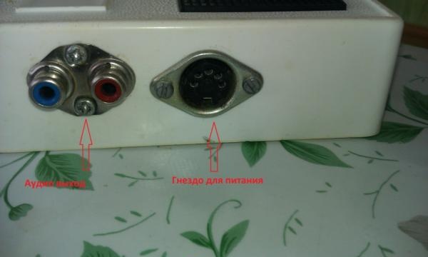
And for audio output I decided to use a jack from a DVD, or from a TV. For power supply I installed a socket and plug from an old electrophone from the 70s. These things can also be found in old televisions and tape recorders.

Amplifier based on TDA7496SA


As for the diode bridge, when I assembled it on the KD202 they showed the worst side, the sound was not clear, although these diodes are used in audio equipment. I installed D226 and there are no problems. I decided not to show the power supply because she was the size of a fist. Any self-respecting radio amateur has the same D226 diodes.

Amplifier connected


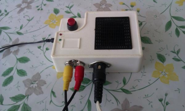
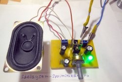
This is a ready-made amplifier. Capacitors must be placed after the diode bridge of at least 1000 microfarads. Try to at least connect two of these in parallel. The more capacitors, the less noise (background) of alternating voltage will be, and this is very important for high-quality and clear sound. I wrote all this for beginners...
come back
Comment
  • bowtiesmilelaughingblushsmileyrelaxed relaxedsmirk
    heart_eyeskissing_heartkissing_closed_eyesflushedrelievedsatisfiedgrin
    winkstuck_out_tongue_winking_eyestuck_out_tongue_closed_eyesgrinningkissingstuck_out_tonguesleeping
    worriedfrowninganguishedopen_mouthgrimacingconfusedhushed
    expressionlessunamusedsweat_smilesweatdisappointed_relievedwearypassive
    disappointedconfoundedfearfulcold_sweatperseverecrysob
    joyastonishedscreamtired_faceangryragetriumph
    sleepyyummasksunglassesdizzy_faceimpsmiling_imp
    neutral_faceno_mouthinnocent
4 minus one =
Comments (3)
  1. Peter
    #1 Peter Guests January 16, 2014 08:55
    3
    1. And the Russian language needs to be learned.....!
    2. And who needs a 5 W amplifier?
  2. Max
    #2 Max Guests November 30, 2015 01:28
    2
    helped from the bottom of my heart)
  3. soup trouper
    #3 soup trouper Guests 16 June 2019 14:29
    4
    Great is the mighty Russian language! :))
    It’s just not clear why it was necessary to pick out the m/circuit from the TV board in order to then plug it into the HZ board. from what?
    I would break off a piece of the board where it stood, solder out the parts not related to the ULF circuit, cut off the excess with a grinder - and enjoy HiFi sound 2x5 W))
    And, by the way, by applying voltage to pin 3, you can synchronously adjust the volume of the amplifier without any crackles or rustles (see the datasheet for details).

Simple table with benches for the garden with your own hands

New Year's toys for decorating a street spruce or pine tree | Do it yourself

How to simply seal a plastic barrel

Decorating a family calendar | Do it yourself

«Do it yourself - with your own hands» - a site of interesting homemade products made from scrap materials and items at home. Step-by-step master classes with photos and descriptions, technologies, life hacks - everything a real master or just a craftsman needs for needlework. Crafts of any complexity, a large selection of directions and ideas for creativity.

We recommend reading

Washing machine error codes