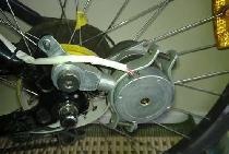
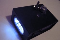
For example: the stepper motor, which is so common, is usually used by DIYers as a mini generator for a flashlight or something else. But I have almost never seen it used specifically as a motor to convert electrical energy into mechanical energy. This is understandable: to control a stepper motor you need electronics. You can't just connect it to voltage.
And as it turned out, I was wrong. A stepper motor from a printer or some other device is quite easy to start from alternating current.
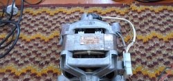
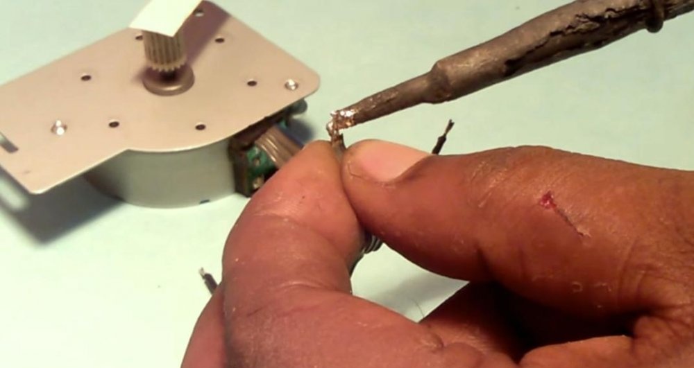
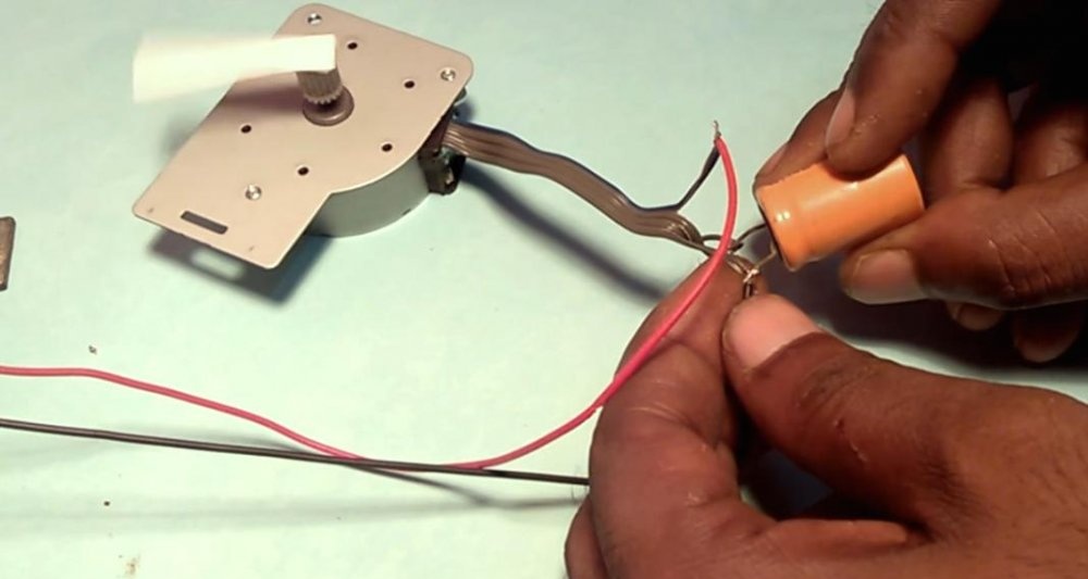
I took this engine.
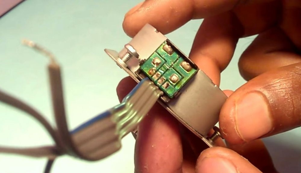
They usually have four terminals and two windings. In most cases, but there are others, of course. I'll look at the most popular one.
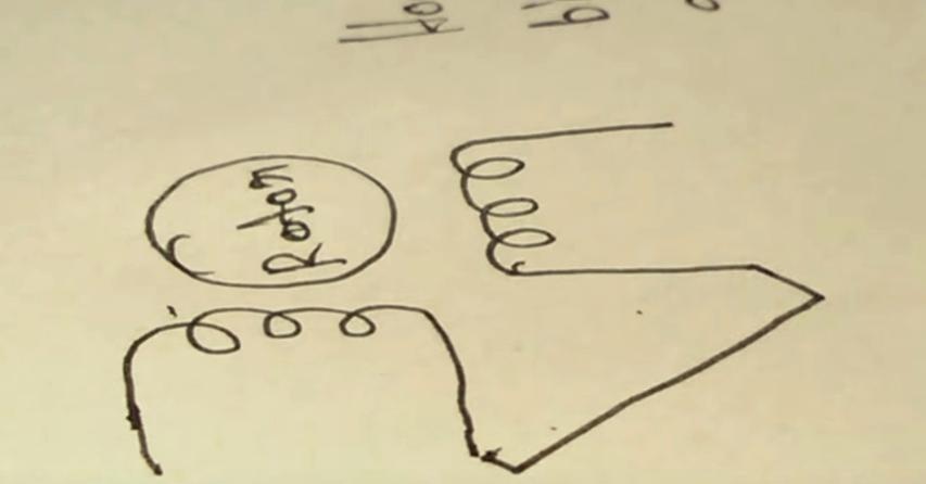
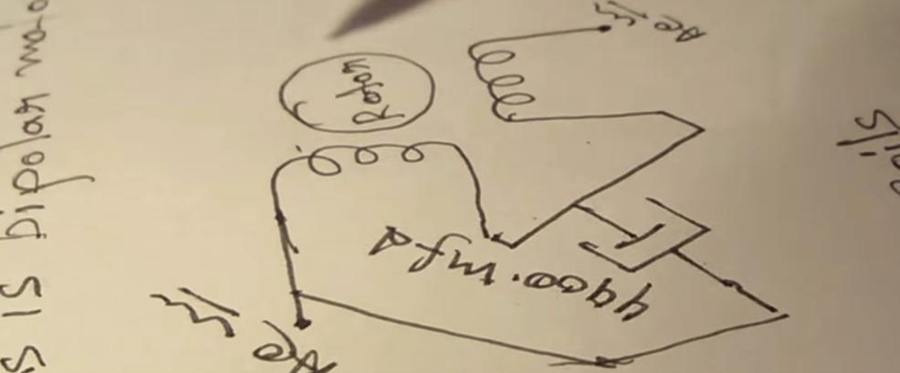
Stepper motor circuit
Its winding diagram looks something like this:
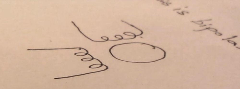
Very similar to the circuit of a conventional asynchronous motor.
To start you will need:
- Capacitor with a capacity of 470-3300 µF.
- 12V AC power supply.
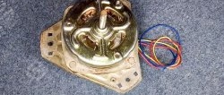
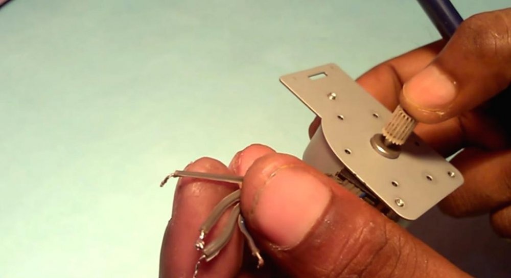
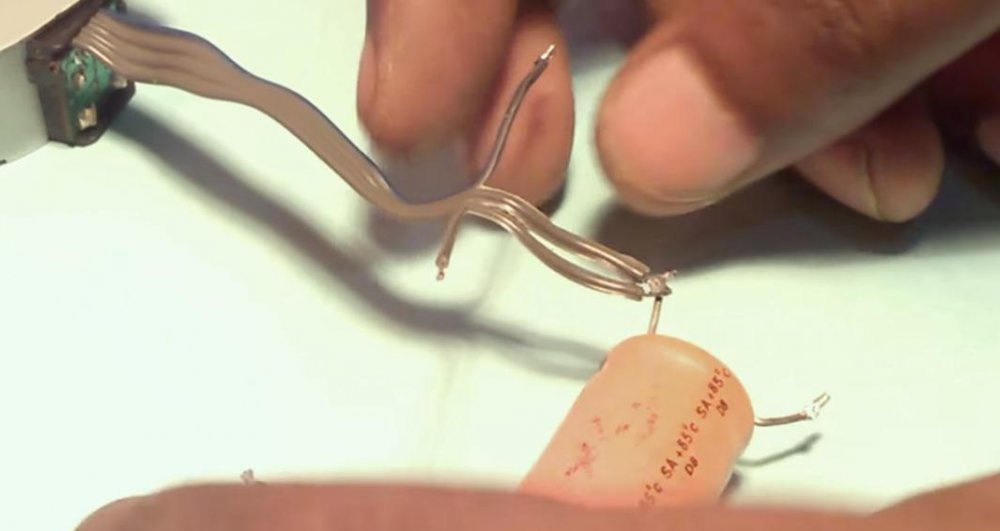
We close the windings in series.
We twist the middle of the wires and solder them.
We connect the capacitor with one terminal to the middle of the windings, and the second terminal to the power source at any output. In fact, the capacitor will be parallel to one of the windings.
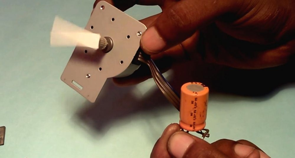
We apply power and the engine starts to spin.
If you transfer the capacitor lead from one power output to another, the motor shaft will begin to rotate in the other direction.
Everything is extremely simple. And the principle of operation of all this is very simple: the capacitor forms a phase shift on one of the windings, as a result of which the windings work almost alternately and the stepper motor rotates.
It's a shame that the engine speed cannot be adjusted. Increasing or decreasing the supply voltage will not lead to anything, since the speed is set by the network frequency.
I would like to add that in this example a DC capacitor is used, which is not a completely correct option. And if you decide to use such a connection circuit, take an AC capacitor. You can also do it yourself by connecting two DC capacitors in back-to-back series.