Recently, an activity such as searching for various ancient coins, household items, and just metal trinkets in the ground using a metal detector has become very popular. In fact, what could be better than taking a walk through the field in the morning, inhaling the smells of nature and enjoying the views. And if at the same time you manage to discover some worthwhile find in the ground, then it’s a fairy tale. Some people do this on purpose, spending days combing fields in search of valuable coins or other valuables. They have at their disposal expensive factory-made metal detectors, which not everyone can afford to buy. However, it is quite possible to assemble a full-fledged metal detector yourself.
This article will discuss the creation of the most popular, sought-after, time-tested, reliable pulse metal detector called “Pirate”. It allows you to find coins in the ground at a depth of 15-20 cm and large objects at a distance of up to 1.5 m. The diagram of the metal detector is presented below.
Metal detector circuit "Pirate"
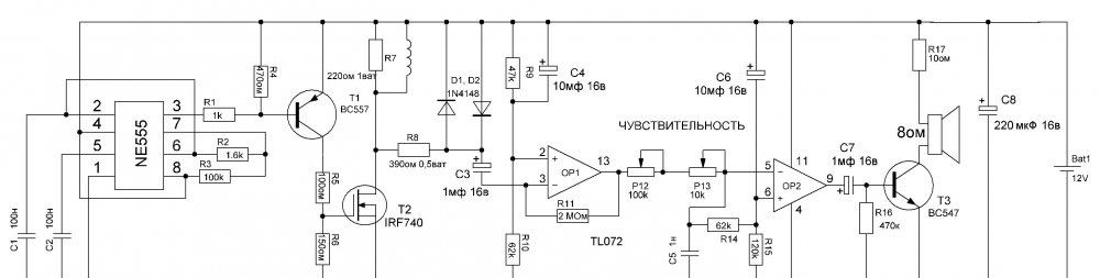
The entire circuit can be divided into two parts - transmitter and receiver.The NE555 microcircuit generates rectangular pulses, which are fed to a coil through a powerful field-effect transistor. When the coil interacts with metal located next to it, complex physical phenomena occur, thanks to which the receiving part has the ability to “see” whether there is metal in the coil area or not. The receiver chip in the original Pirate circuit is the Soviet K157UD2, which is now becoming quite difficult to obtain. However, instead of it, you can use the modern TL072, the parameters of the metal detector will remain exactly the same. The printed circuit board proposed in this article is designed specifically for installing the TL072 chip (they have different pinouts).
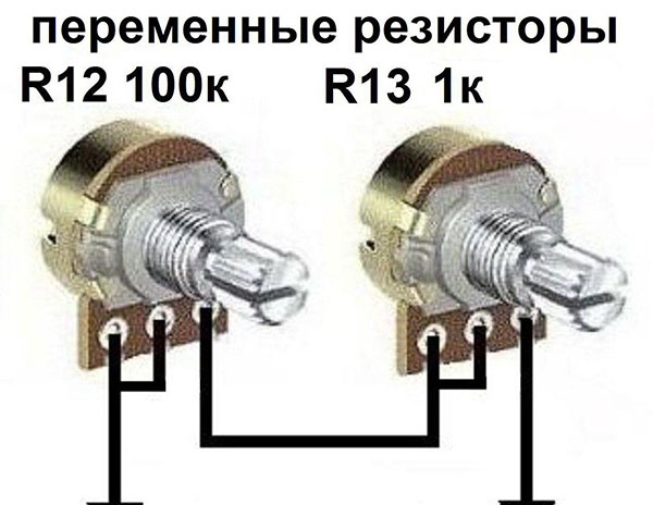
Capacitors C1 and C2 are responsible for generating the frequency of rectangular pulses; their capacitance must be stable, so it is advisable to use film capacitors. Resistors R2 and R3 are responsible for the duration and frequency of the rectangular pulses that the microcircuit generates. From its output they are supplied to transistor T1, inverted and fed to the gate of the field-effect transistor. Here you can use any sufficiently powerful field-effect transistor with a drain-source voltage of at least 200 volts. For example, IRF630, IRF740. Diodes D1 and D2 are any low-power ones, for example, KD521 or 1N4148. Between pins 1 and 6 of the microcircuit, a variable resistor with a nominal value of 100 kOhm is connected, with which the sensitivity is set. It is most convenient to use two potentiometers, 100 kOhm for rough adjustment and 1-10 kOhm for fine adjustment. You can connect them according to the following scheme:
The speaker in the circuit is connected in series with a 10-47 Ohm resistor. The lower its resistance, the louder the sound and the greater the consumption of the metal detector.Transistor T3 can be replaced with any other low-power NPN transistor, for example, with the domestic KT3102. You can use any speaker you find. So, let's move from words to action.
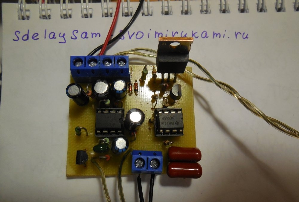
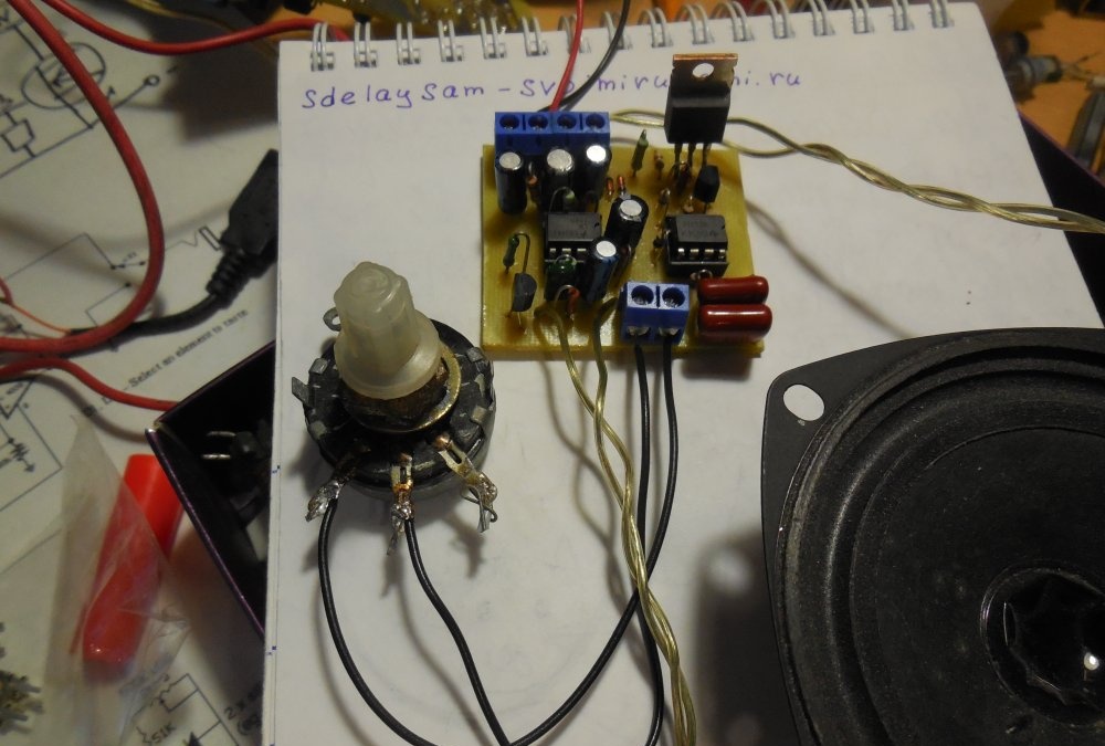
Metal detector assembly
List of required parts
Chips:
- NE555 – 1 pc.
- TL072 – 1 pc.
Transistors:
- BC547 – 1 pc.
- BC557 – 1 pc.
Capacitors:
- 100 nF – 2 pcs.
- 1 nF – 1 pc.
- 10 µF – 2 pcs.
- 1 µF – 2 pcs.
- 220 uF – 1 pc.
Resistors:
- 100 kOhm – 1 pc.
- 1.6 kOhm – 1 pc.
- 1 kOhm – 1 pc.
- 10 Ohm – 2 pcs.
- 150 Ohm – 1 pc.
- 220 Ohm – 1 pc.
- 390 Ohm – 1 pc.
- 47 kOhm – 2 pcs.
- 62 kOhm – 1 pc.
- 2 MOhm – 1 pc.
- 120 kOhm – 1 pc.
- 470 kOhm – 1 pc.
Rest:
- Speaker 1 – pcs.
- Diodes 1N4148 – 2 pcs.
- DIP8 sockets – 2 pcs.
- Potentiometer 100 kOhm – 1 pc.
- Potentiometer 10 kOhm – 1 pc.
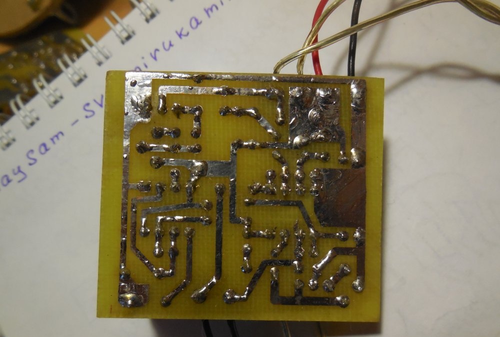
Printed circuit board
The printed circuit board is made using the LUT method; there is no need to mirror it before printing.
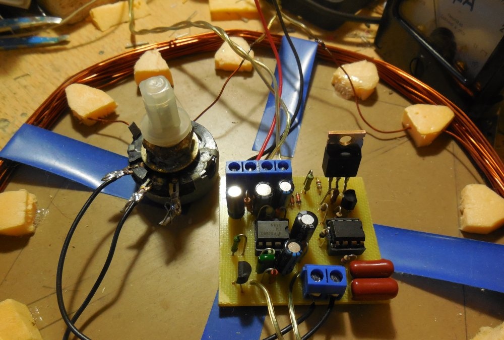
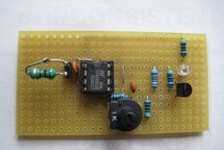
First of all, you need to solder resistors, diodes, then everything else on the board. It is advisable to install the microcircuits in sockets. The wires for connecting the coil, speaker, potentiometer and coil can be soldered directly into the board, but it is more convenient to use screw terminal blocks, then you can connect and disconnect the wires without using a soldering iron.
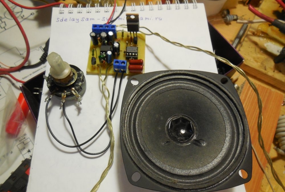
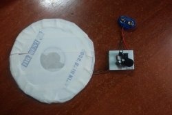
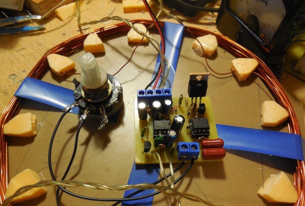
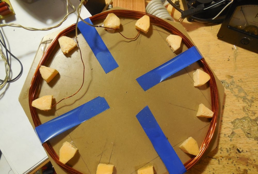
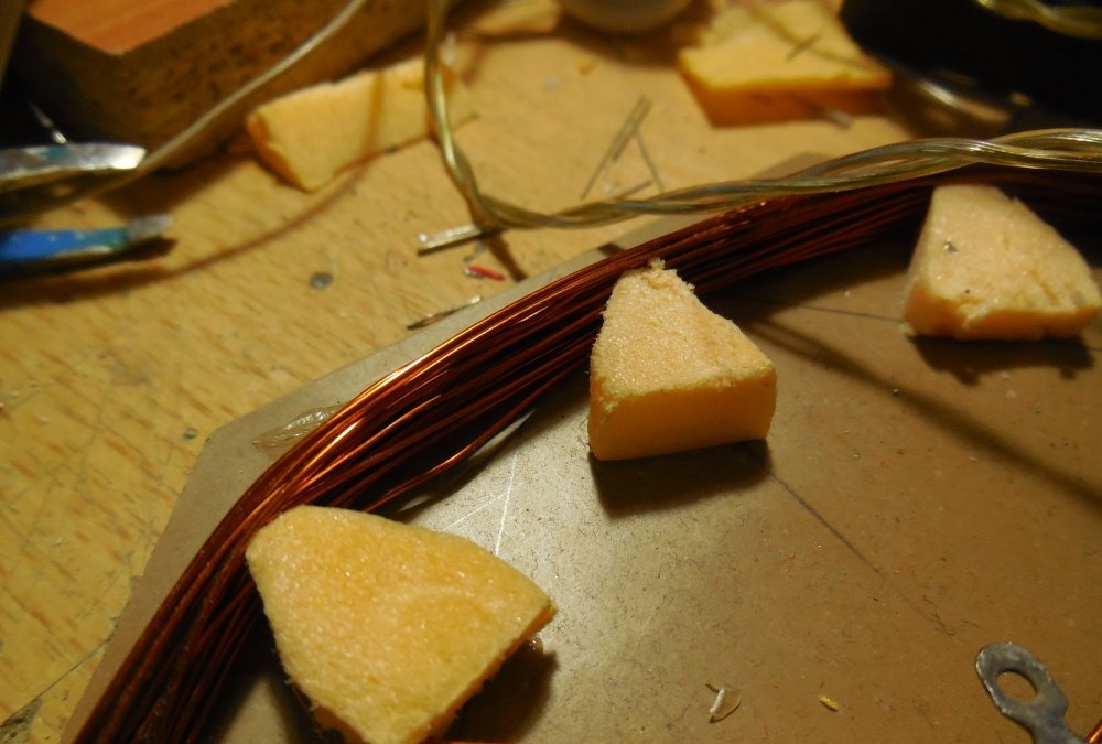
Making a coil
A few words about the search coil. The best option is to wind 20-25 turns of copper wire with a cross-section of 0.5 mm2 on a round frame with a diameter of about 20 cm. Sensitivity largely depends on the number of turns, so you should first wind more turns, about 30, and then gradually reducing the number of turns , choose a number at which the sensitivity will be maximum.The wires from the board to the coil should not be long, preferably copper and with a cross-section no smaller than the cross-section of the coil wire.
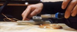
Setting up a metal detector
After assembling the board and winding the coil, the device can be turned on. In the first 5-10 seconds after switching on, various noises and crackles will be heard from the speaker, this is normal. Then, when the operational amplifier enters its operating mode, you need to use the potentiometer to find a mode when individual clicks will be heard from the speaker. When you bring a metal object to the coil, the frequency of clicks will increase significantly, and if you bring the metal into the very center of the coil, the sound will turn into a continuous hum. If the sensitivity is not enough, and changing the number of coil turns does not help, you should try to select the values of resistors R7, R11, changing them up or down. The board must be cleaned of flux; it often causes the metal detector to malfunction. Happy build!