Do it yourself
Life hacks, master classes, useful tips, recipes.
home » Electronics » Simple circuits » Automatic cooler speed controller

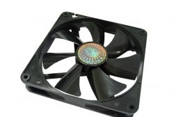
Cooling fans are now found in many household appliances, be it computers, stereo systems, or home theaters. They do their job well, cool the heating elements, but at the same time they emit a heart-rending and very annoying noise. This is especially critical in stereo systems and home theaters, because fan noise can interfere with enjoying your favorite music. Manufacturers often save money and connect cooling fans directly to the power supply, which makes them always rotate at maximum speed, regardless of whether cooling is currently required or not. You can solve this problem quite simply - build in your own automatic cooler speed controller. It will monitor the temperature of the radiator and only turn on cooling if necessary, and if the temperature continues to rise, the regulator will increase the cooler speed up to the maximum. In addition to reducing noise, such a device will significantly increase the service life of the fan itself. It can also be used, for example, when creating homemade powerful amplifiers, power supplies or other electronic devices.

Scheme

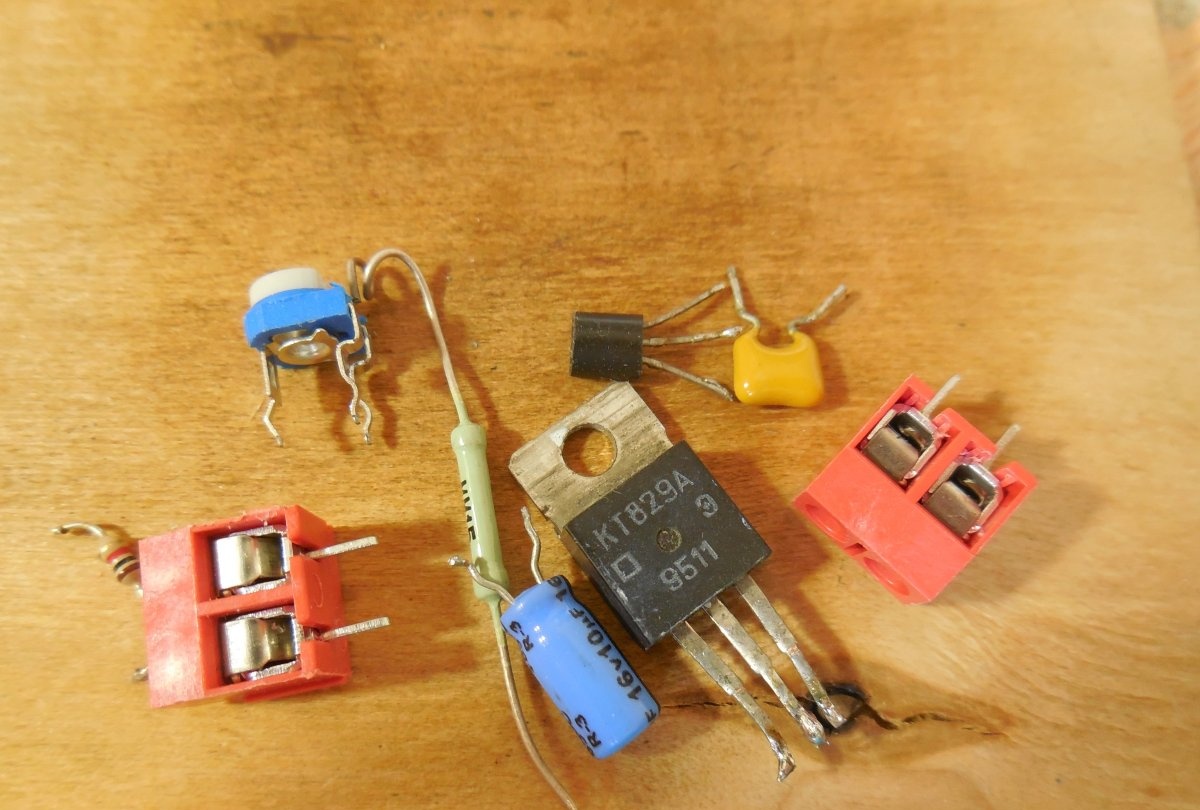
The circuit is extremely simple, containing only two transistors, a couple of resistors and a thermistor, but nevertheless it works great. M1 in the diagram is a fan whose speed will be regulated. The circuit is designed to use standard 12-volt coolers. VT1 – low-power n-p-n transistor, for example, KT3102B, BC547B, KT315B. Here it is advisable to use transistors with a gain of 300 or more. VT2 is a powerful npn transistor; it is the one that switches the fan. You can use inexpensive domestic KT819, KT829, again it is advisable to choose a transistor with a high gain. R1 is a thermistor (also called a thermistor), a key link in the circuit. It changes its resistance depending on the temperature. Any NTC thermistor with a resistance of 10-200 kOhm, for example, the domestic MMT-4, is suitable here. The value of the tuning resistor R2 depends on the choice of thermistor; it should be 1.5 - 2 times larger. This resistor sets the threshold for turning on the fan.

Manufacturing of the regulator

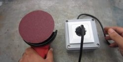
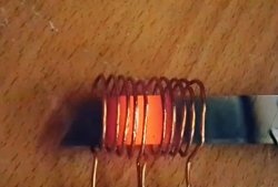
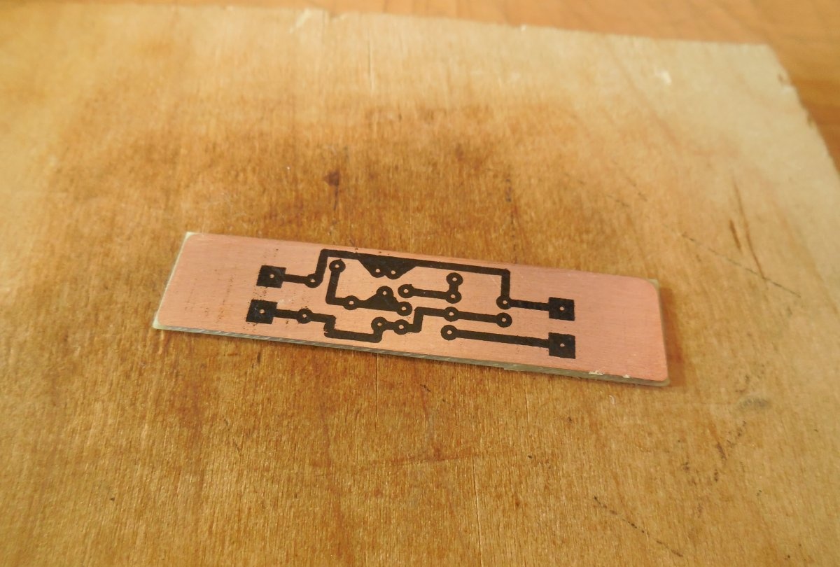
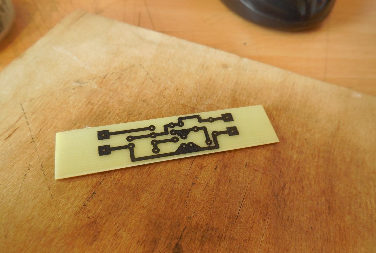
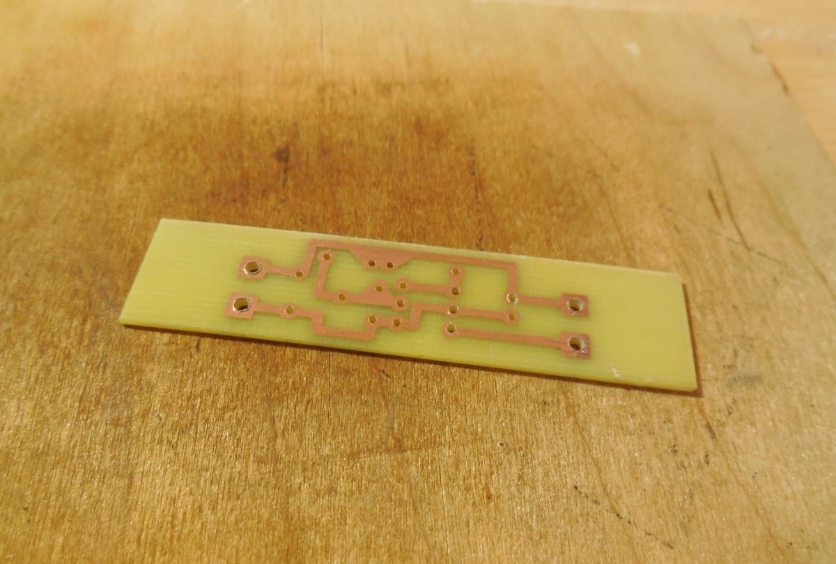
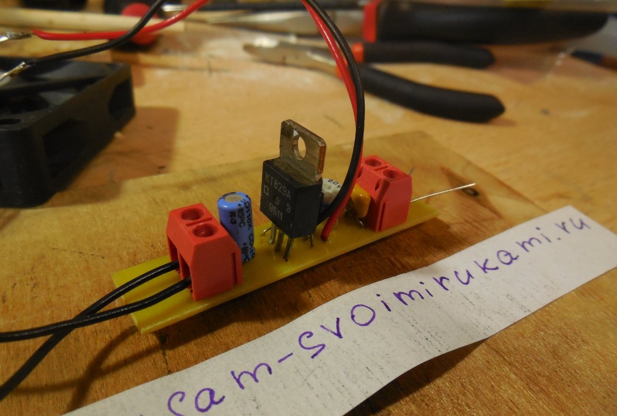
The circuit can be easily assembled using surface mounting, or you can make a printed circuit board, which is what I did. To connect the power wires and the fan itself, terminal blocks are provided on the board, and the thermistor is output on a pair of wires and attached to the radiator. For greater thermal conductivity, you need to attach it using thermal paste. The board is made using the LUT method; below are several photographs of the process.

Download the board:
shema.zip [2.09 Kb] (downloads: 2201)

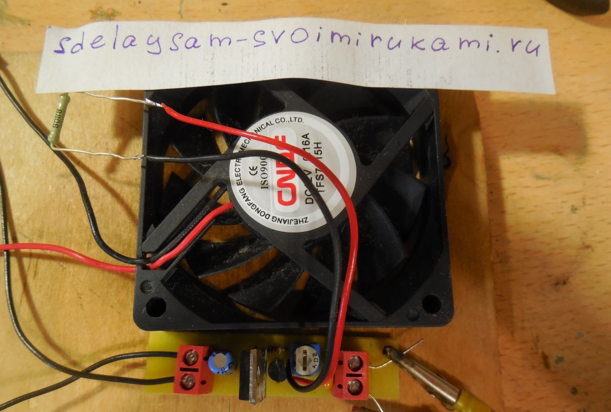
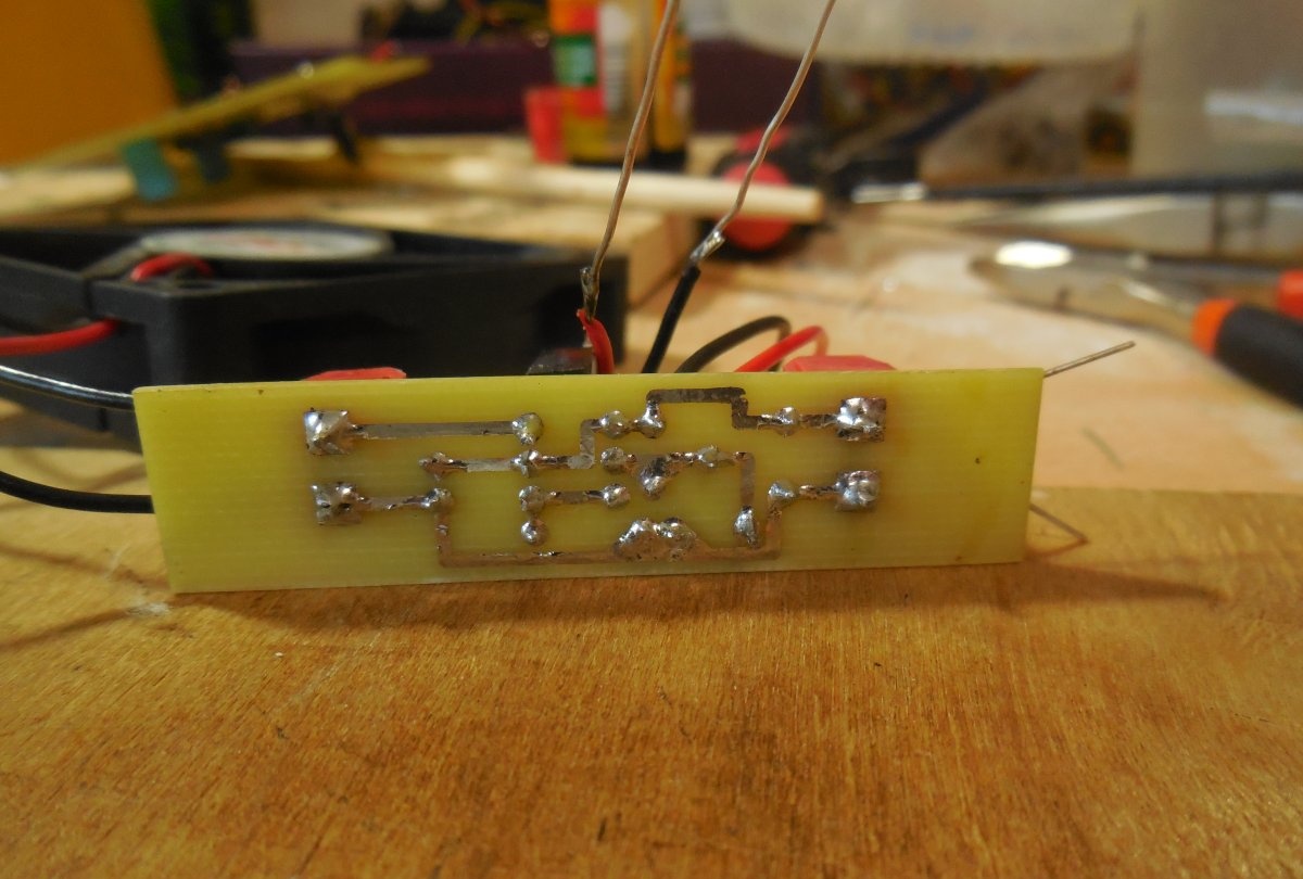
After making the board, parts are soldered into it, as usual, first small, then large. It is worth paying attention to the pinout of the transistors in order to solder them correctly.After completing the assembly, the board must be washed from flux residues, the tracks must be ringed, and the installation must be ensured correctly.

Settings

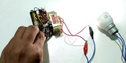
Now you can connect the fan to the board and carefully supply power by setting the trimming resistor to the minimum position (VT1 base is pulled to ground). The fan should not rotate. Then, smoothly turning R2, you need to find the moment when the fan starts to rotate slightly at minimum speed and turn the trimmer back just a little so that it stops rotating. Now you can check the operation of the regulator - just put your finger on the thermistor and the fan will start rotating again. Thus, when the radiator temperature is equal to room temperature, the fan does not spin, but as soon as it rises even a little, it will immediately begin to cool.

come back
Comment
  • bowtiesmilelaughingblushsmileyrelaxed relaxedsmirk
    heart_eyeskissing_heartkissing_closed_eyesflushedrelievedsatisfiedgrin
    winkstuck_out_tongue_winking_eyestuck_out_tongue_closed_eyesgrinningkissingstuck_out_tonguesleeping
    worriedfrowninganguishedopen_mouthgrimacingconfusedhushed
    expressionlessunamusedsweat_smilesweatdisappointed_relievedwearypassive
    disappointedconfoundedfearfulcold_sweatperseverecrysob
    joyastonishedscreamtired_faceangryragetriumph
    sleepyyummasksunglassesdizzy_faceimpsmiling_imp
    neutral_faceno_mouthinnocent
3+three=
Comments (15)
  1. Stepan
    #1 Stepan Guests 18 June 2018 18:36
    5
    Thank you.
  2. Konstantin
    #2 Konstantin Guests 14 September 2018 10:36
    2
    why are the capacitors not indicated on the diagram, but on the board... and their values
    1. Maksim
      #3 Maksim Guests 30 September 2018 15:41
      1
      16v 10mF
      1. Danila Voropaev
        #4 Danila Voropaev Guests 20 February 2019 23:36
        2
        Comrades, please tell me the operating principle of this device, what each of the components is needed for. Very necessary. Thank you!
  3. Guest Vlad
    #5 Guest Vlad Guests 15 October 2018 12:04
    8
    What is the value of the orange capacitor?
  4. Guest Andrey
    #6 Guest Andrey Guests November 16, 2018 11:10
    5
    Please provide a complete list of all parts and a complete circuit with capacitors.
  5. Drosselmeyer
    #7 Drosselmeyer Guests November 22, 2019 10:19
    3
    In this circuit, in principle, capacitors are not needed. According to the wiring, the electrolyte and ceramic capacitor are powered. You can bet, you can not.
  6. artem
    #8 artem Guests 29 November 2019 20:03
    1
    But how can I make the cooler speed increase cyclically: a few seconds fast speed, then slower and faster again, etc.? Needed to adjust the cooler to simulate artificial fire (adjust water vapor) for greater realism
  7. Dmitriy
    #9 Dmitriy Guests 6 December 2019 14:28
    1
    Please tell me how to power such an assembly?
  8. Pochik Kobaki
    #10 Pochik Kobaki Guests 15 December 2019 13:51
    4
    This circuit has one feature: since the transistors are connected according to a circuit with a common collector, the voltage at the emitter of each transistor will be ~ 0.6 less, for a total voltage drop of 1.8 volts (since the KT829 is composite, the drop across it is 1.2 V ). The output voltage in this circuit will be no more than 10V, therefore the fan will not have time to work at full power.
  9. Jeyhun
    #11 Jeyhun Guests April 28, 2020 00:53
    3
    Thank you. there will be something to keep my niece occupied in quarantine
  10. Arthur
    #12 Arthur Guests 20 August 2020 09:49
    3
    Or you can get by with just one field worker...
    Now I generally use it with thermo-relay - it’s easier and cheaper.

Clay toys | Do it yourself

Do it yourself - crafts and master classes | Page 203

Do-it-yourself insulation of a balcony

“Zero” and “ground”: what is the fundamental difference?

«Do it yourself - with your own hands» - a site of interesting homemade products made from scrap materials and items at home. Step-by-step master classes with photos and descriptions, technologies, life hacks - everything a real master or just a craftsman needs for needlework. Crafts of any complexity, a large selection of directions and ideas for creativity.

We recommend reading

Washing machine error codes