In everyday life, solid-state relays are increasingly taking their place; they are simply not replaceable when the load is turned on and off very often and ordinary electromagnetic relays simply cannot withstand mechanical loads, wear out and break. In addition, these annoying clicks when turning the load on and off clearly favor the use of solid-state relays, which are absolutely silent.
However, the price of these new relays, especially three-phase ones, makes us think about the feasibility of their use. In this case, making such a relay yourself can help, and this site will help you with this. Making a three-phase 40 ampere relay with your own hands will cost you a maximum of 500 rubles, even if you buy all the parts, while a factory one costs several thousand. It's worth thinking about. Right?
The factory relay, if parts of the internal device are damaged, cannot be repaired and requires complete replacement.A homemade relay, made with your own hands, will serve you for many years, because you will thoroughly know its structure, and if any of its parts burn out, you can change them without any problems and continue using this very useful device.
So let's get started.
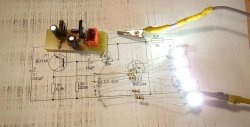
Solid state relay circuit
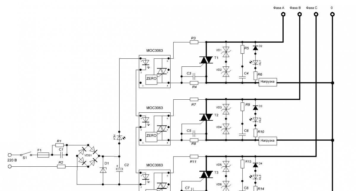
Details
We will need it for work.
- S1 – Any switch or toggle switch.
- F1 – fuse 0.25 – 0.5 Ampere.
- C1 – 0.068 uF 630 Volts.
- R1 – 470 kOhm.
- R2 – 100 Ohm.
- VDS1 – Rectifier bridge 1 Ampere 600 – 1000 Volts or separate diodes.
- D1 – zener diode 20 Volt 0.5 Watt.
- C2 – 10 uF 25 Volts.
- HL4 – any signal Light-emitting diode.
- MOC3063 – 3 pieces.
- R3, 7, 11 at 330 Ohm 0.5 Watt.
- C3, 5, 7 – 2.7 nF each 50 Volts. For current up to 10 Amps per phase. If you are planning a higher load, then you need to set it to 3.3 nF.
- R4, 8, 12 at 470 Ohm 2 Watts. For current up to 10 Amps per phase. If you are planning a higher load, then you need to install 330 Ohm 2 Watts.
- T1, 2, 3 – triacs VTA41-600 – 3 pieces.
- VD1, 2, 3, 4, 5, 6 – protective TVS diodes type 1.5 KE300CA.
- R5, 9, 13 – 47 Ohm 5 Watt each. For current up to 10 Amps per phase. If you are planning a higher load, then you need to install 27 Ohm 5 Watt.
- C4, 6, 8 – 0.047 uF each 630 Volts. For current up to 10 Amps per phase. If you are planning a higher load, then you need to install 0.1 uF 630 Volts.
- D2, 3, 4 – any diodes with a voltage of at least 600 Volts. For example 1N4007.
- HL1, 2, 3 – any signal LEDs.
- R6, 10, 14 – 470 kOhm each.
- Breadboard – 2 pieces.
- Thermally conductive paste.
Manufacturing of three-phase solid state relay
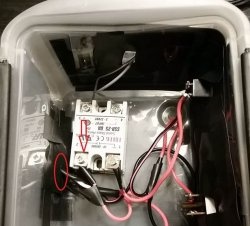
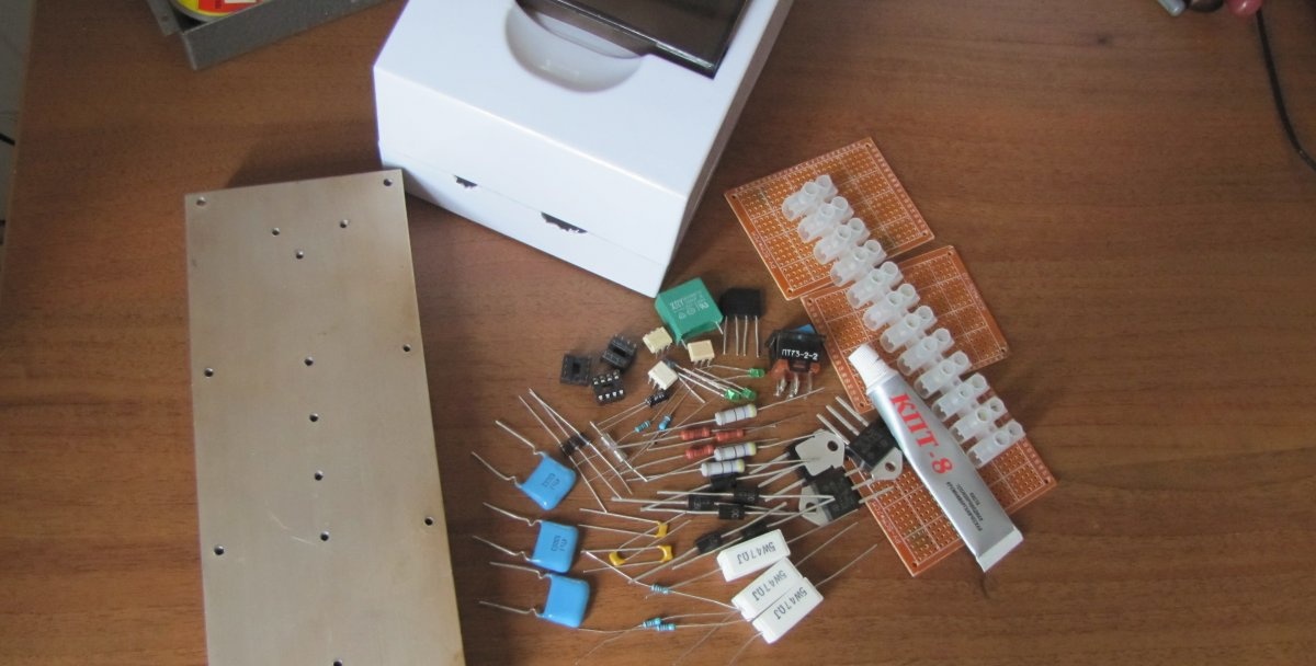
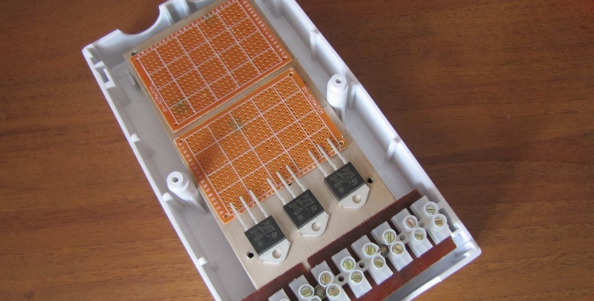
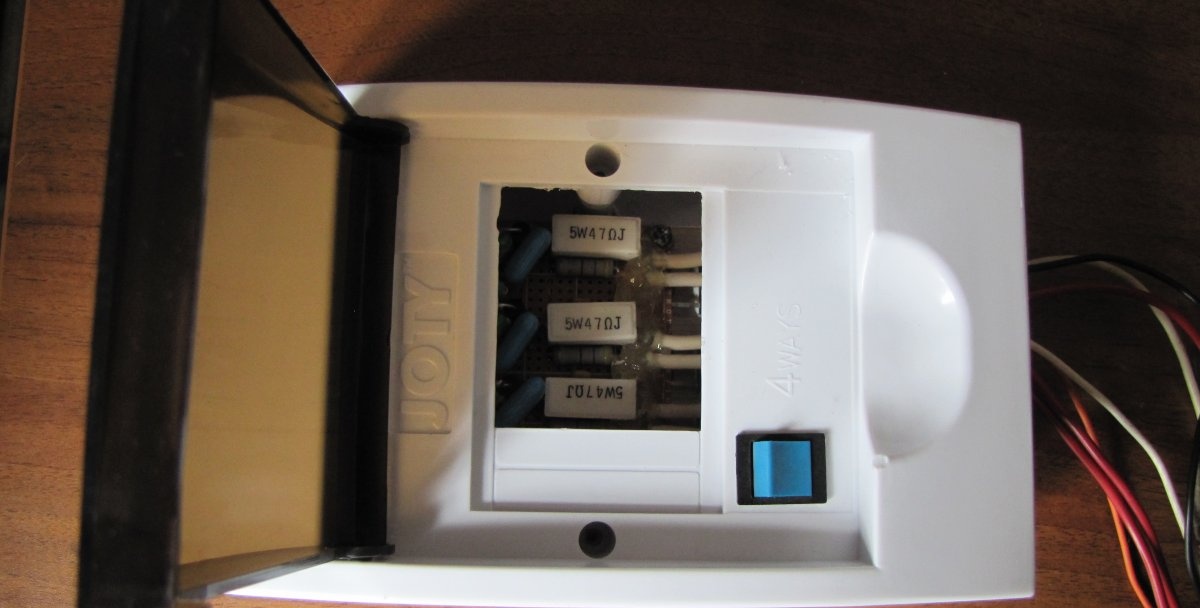
It is best to start collecting parts from the body of the future device. Circuit breaker boxes, which are sold in electrical supply stores, are well suited for this purpose.The price is quite affordable and depends on the size of the box.
The most important part of the future relay is the radiator for cooling the triacs. The more comfortable the temperature for the triacs during operation, the longer they will “live”. In a word, the radiator should be as large as possible (within reasonable limits). If the body of the future relay is metal, then the radiator plate can be tightly screwed to its back wall, and then the entire case will be a large radiator.
VTA-41 triacs can be screwed without insulators, directly to the radiator, since their terminals have no electrical contact with the substrate. For other triacs, it is necessary to check the data.
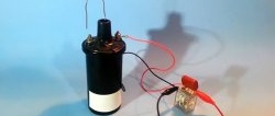
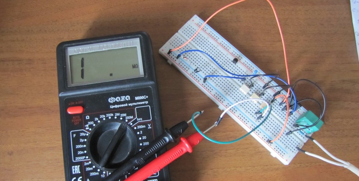
Before installing the circuit parts on the board, I tested the operation of the optocouplers, the photo shows how. Of the 20 pieces of MOS3063 purchased in China, 3 turned out to be defective. So be careful.
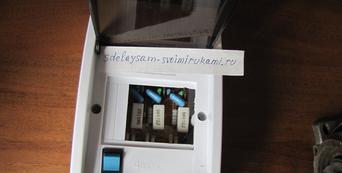
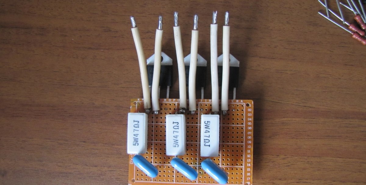
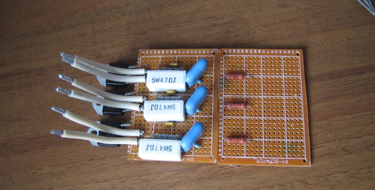
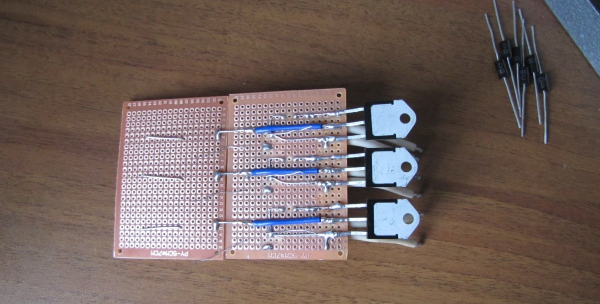
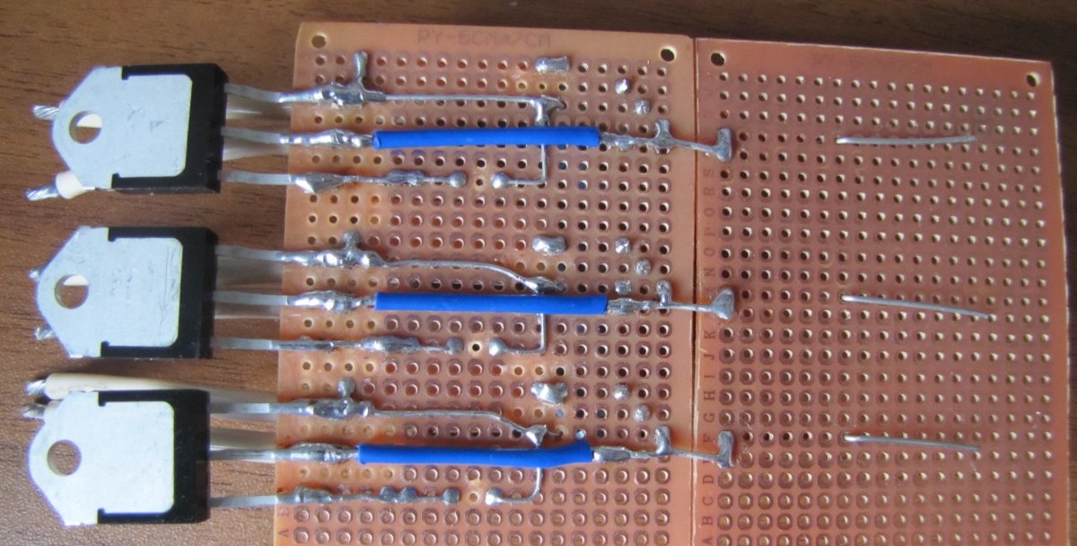
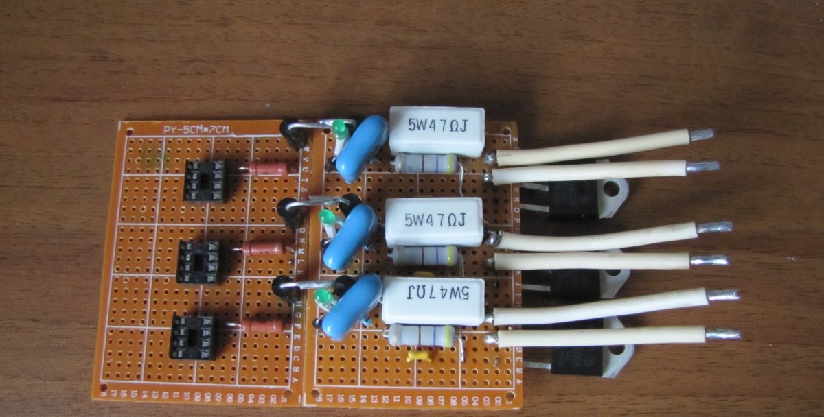
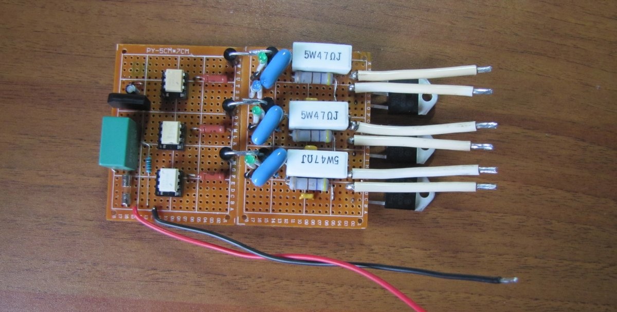
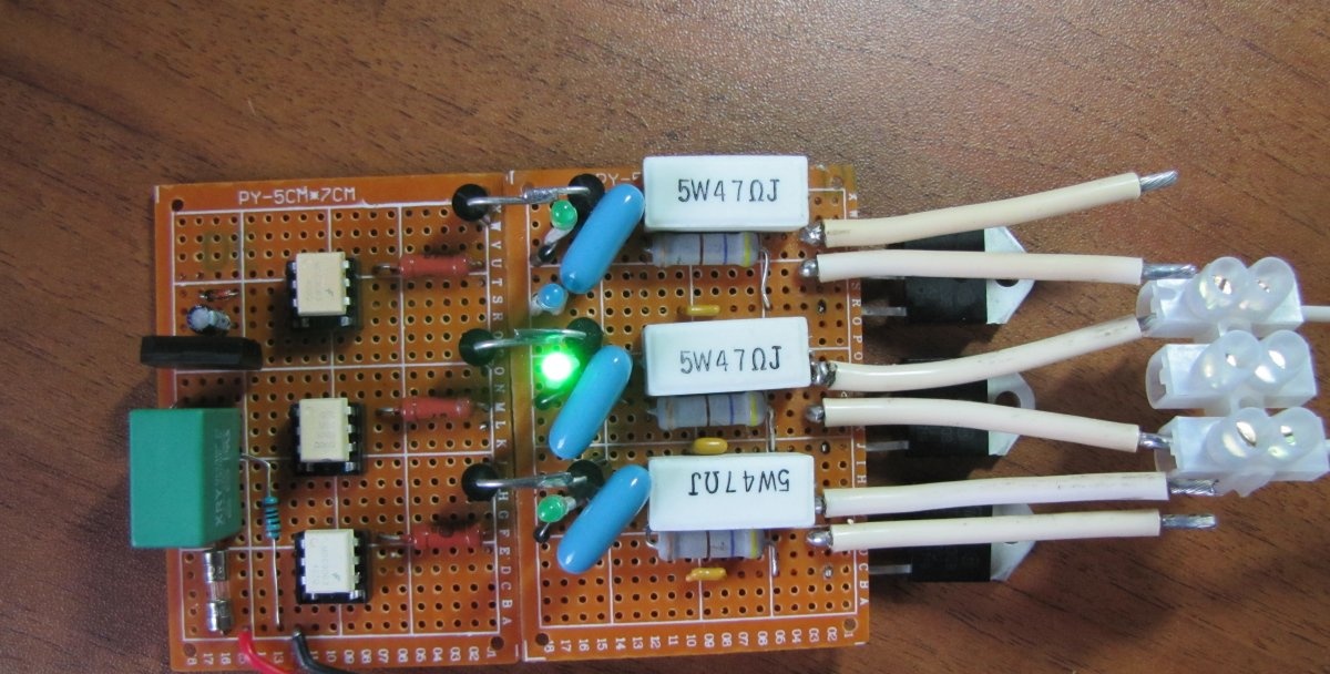
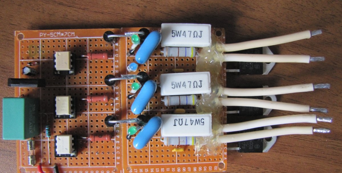
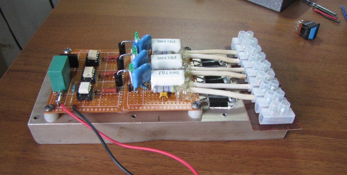
We begin the installation by marking and installing the triacs, and then the remaining parts.
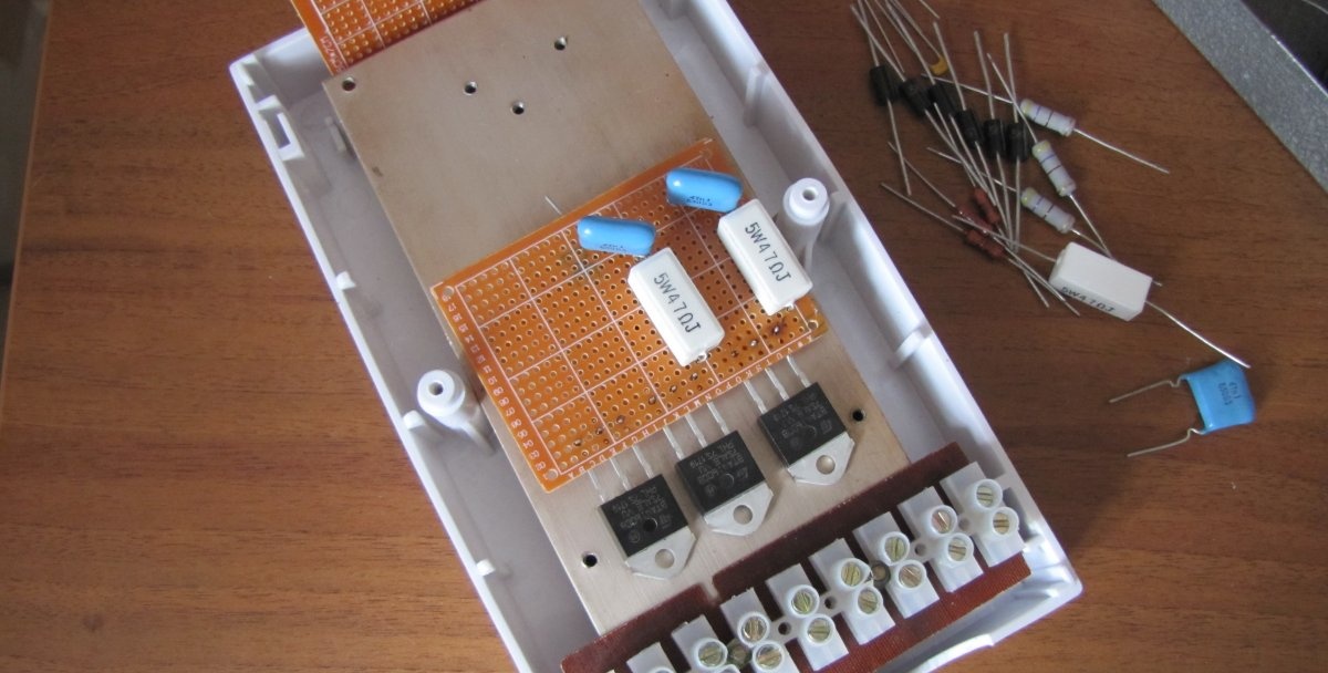
We solder. We solder the wires with a larger diameter (depending on the load).
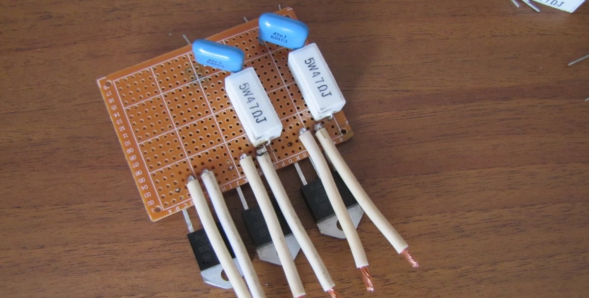
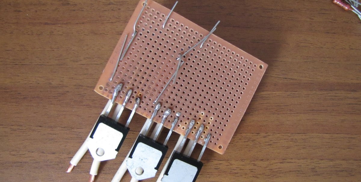
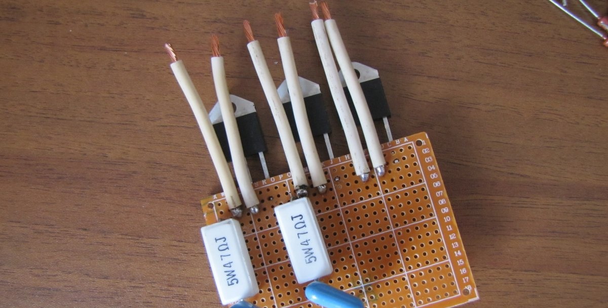
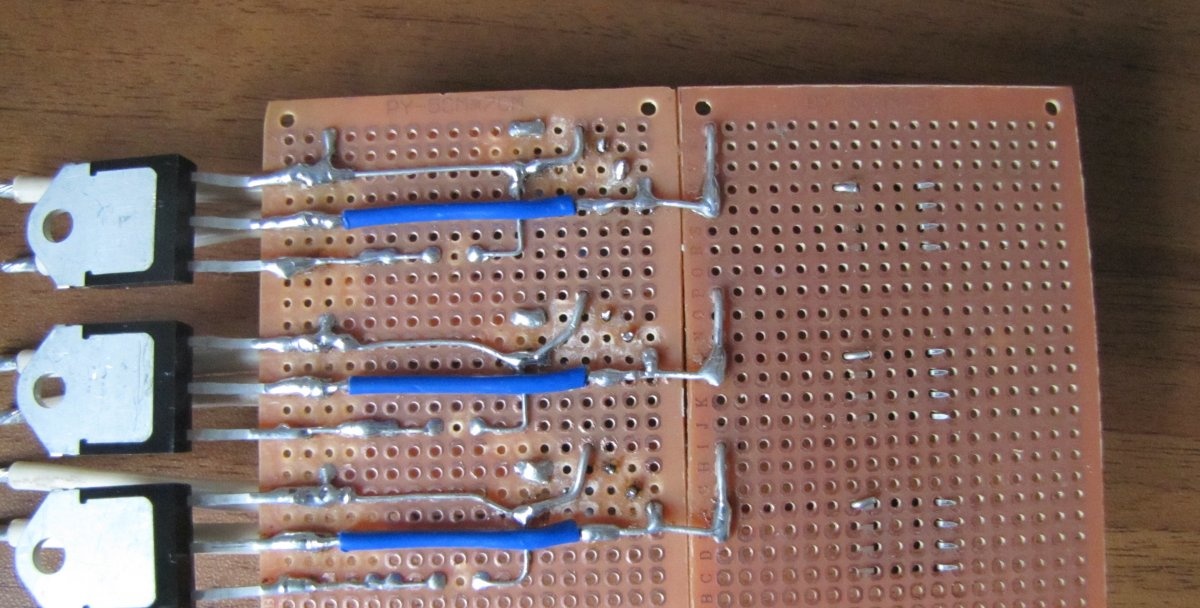
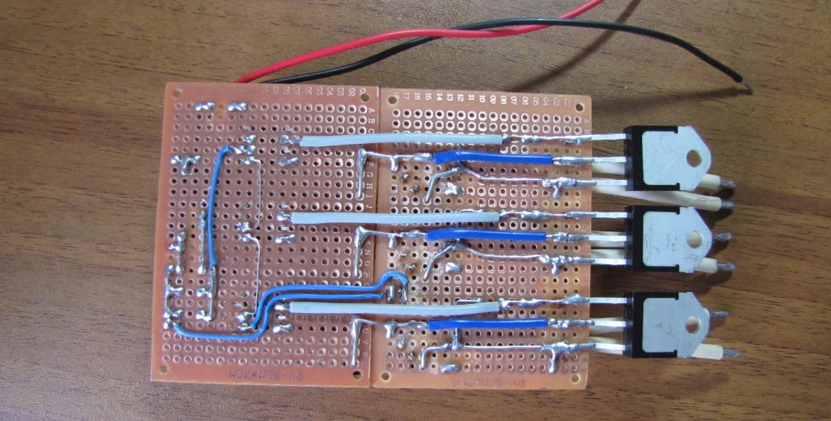
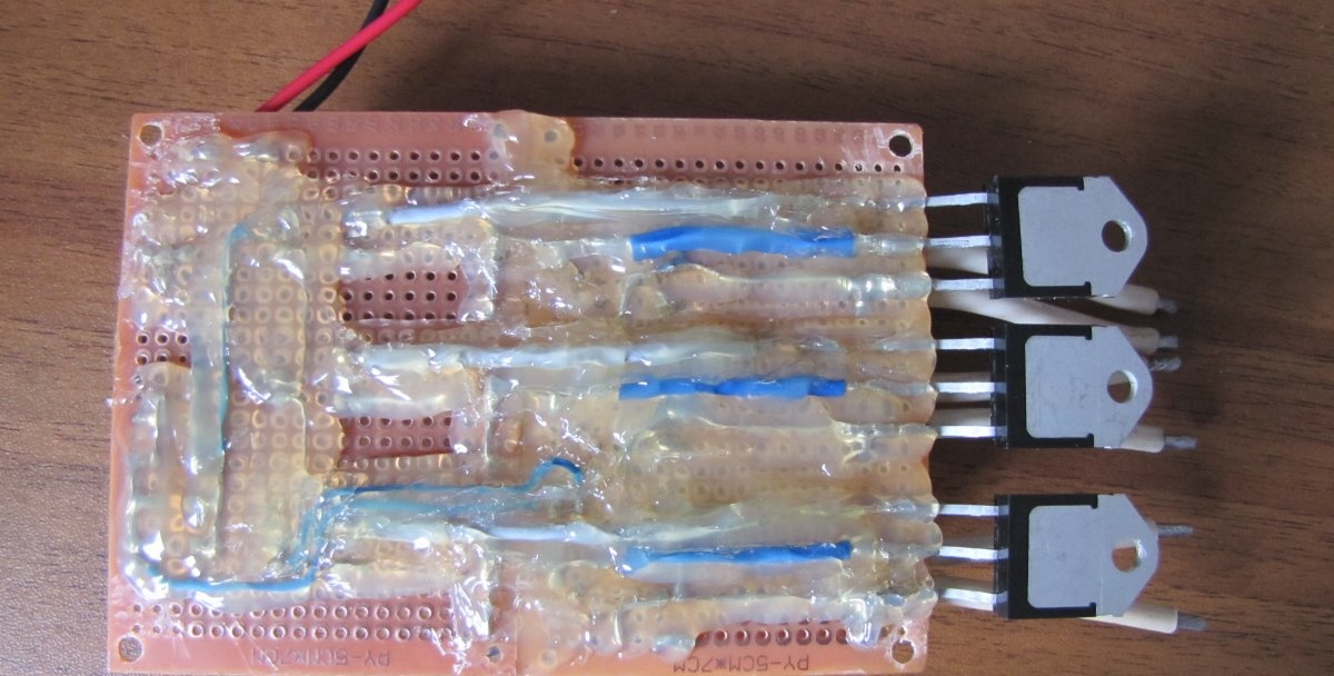
We very carefully remove excess copper contact pads on the breadboard between the high-voltage wires (as in the photographs) to avoid short circuits. 380 Volts is a very high voltage and life-threatening.
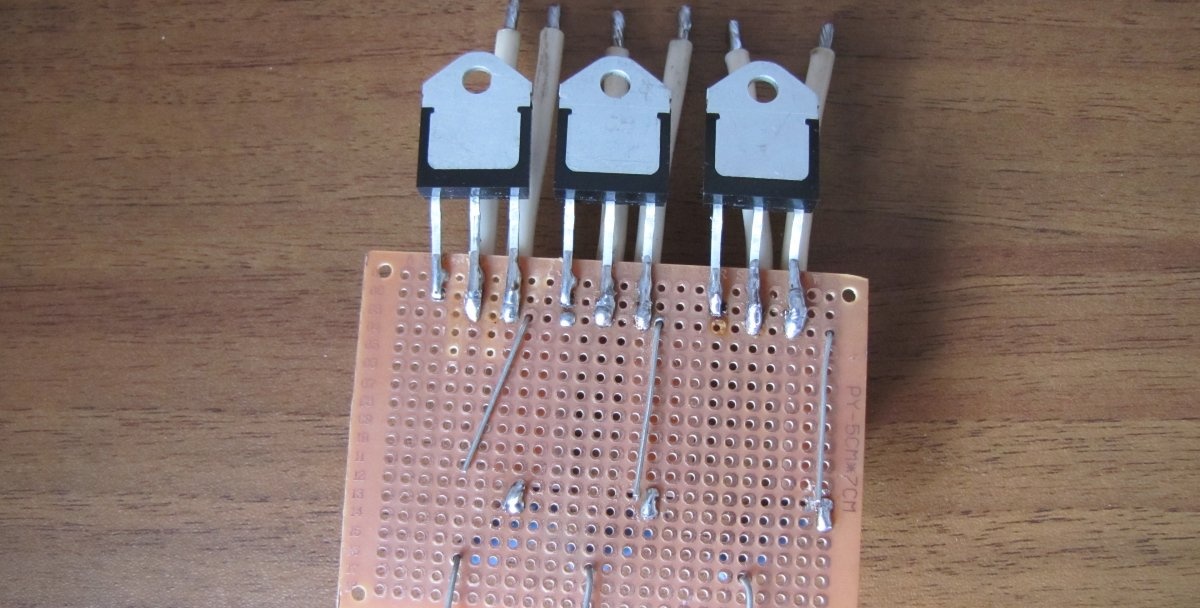
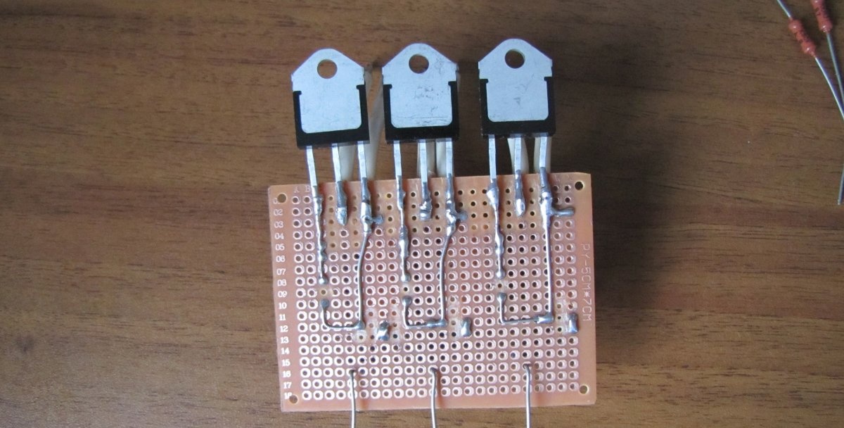
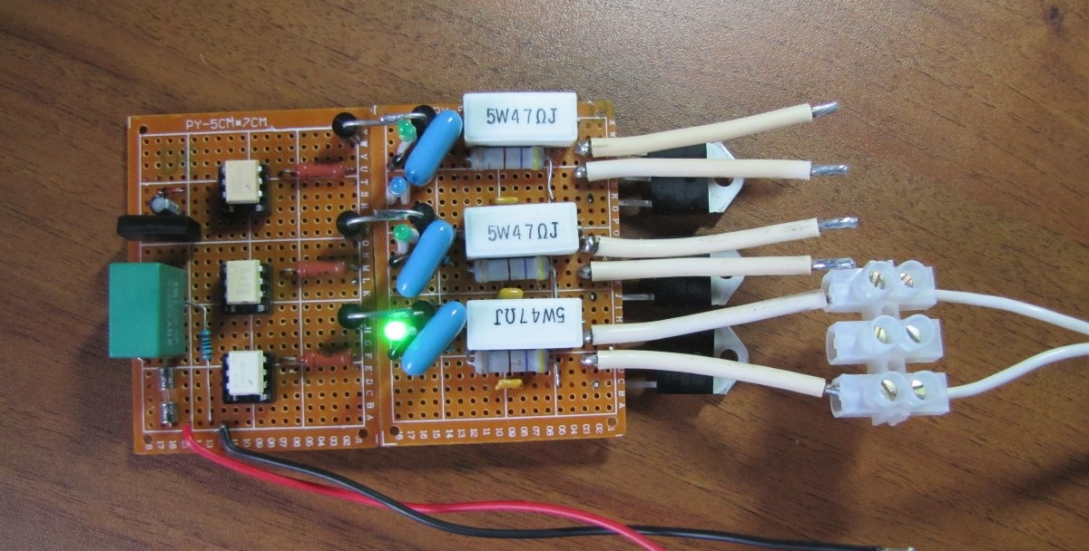
We attach the leads of the parts to the following board.
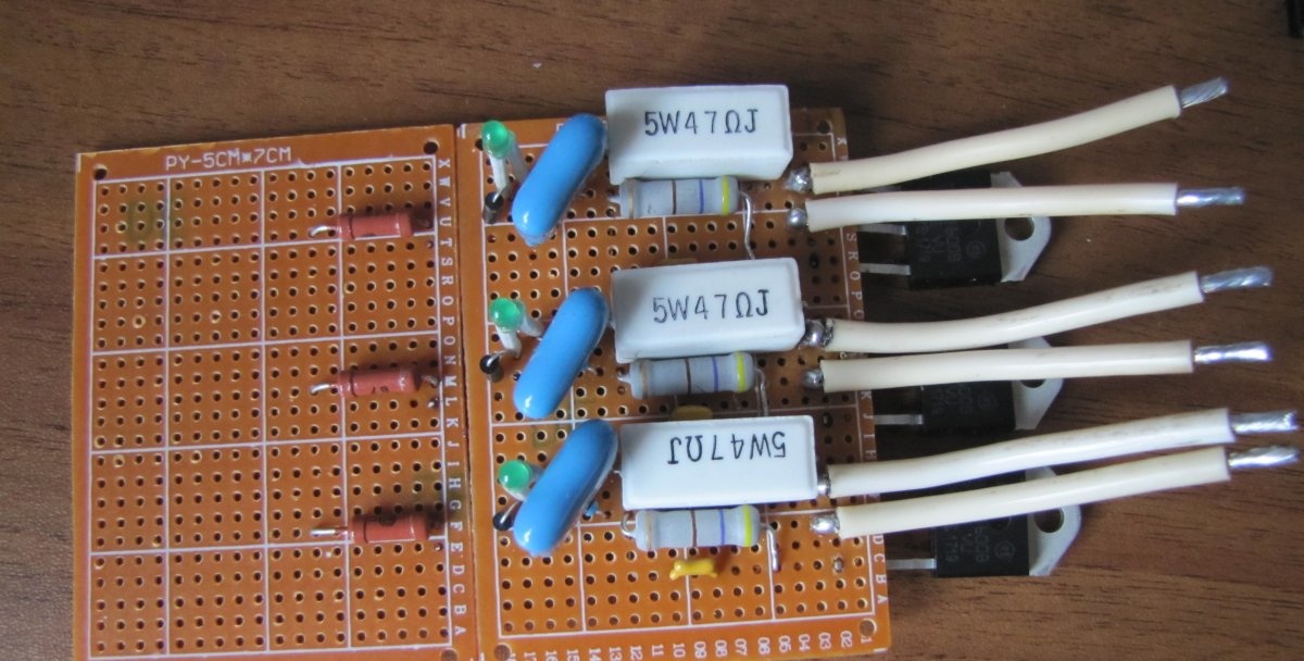
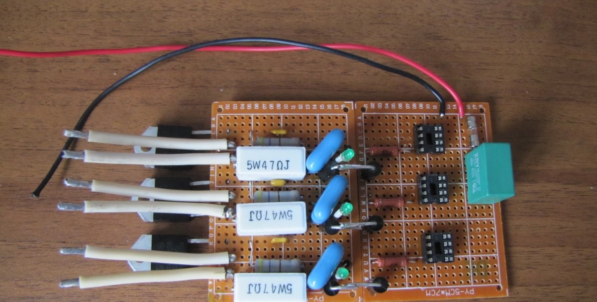
We install sockets for optocouplers. If an optocoupler burns out during operation, it can be replaced in a couple of seconds.
Installing control parts.
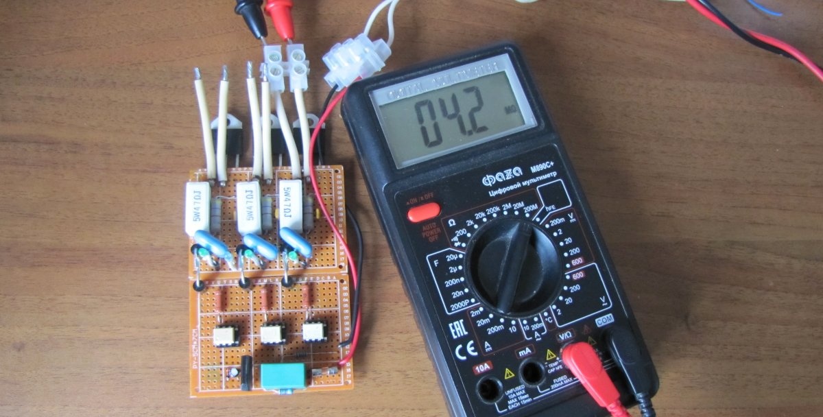
We test the operation of optocouplers.
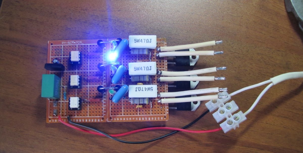
We alternately apply 220 Volts to each phase for testing.
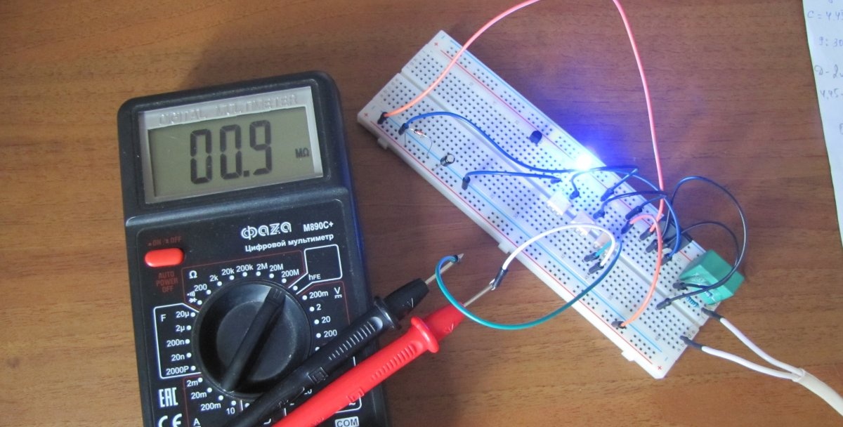
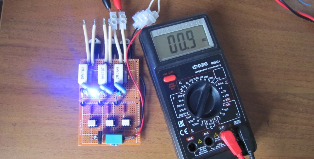
We connect the device to each phase in turn and check the opening of the triac when the control voltage is turned on. 4.2 mOhm – triac is closed.
The triac is open.
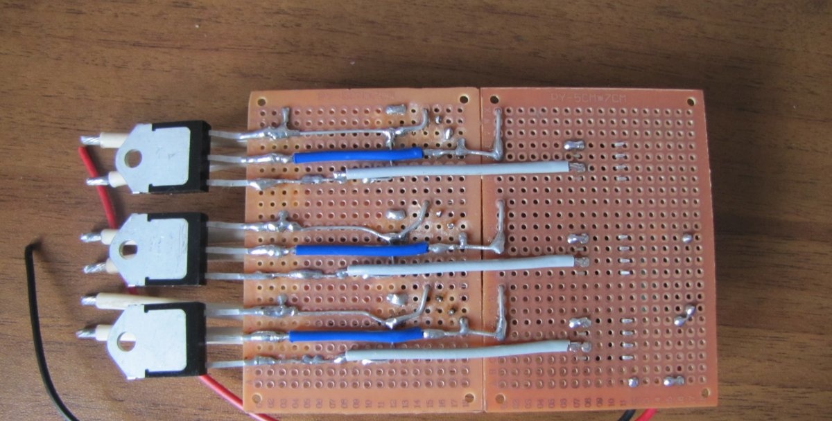
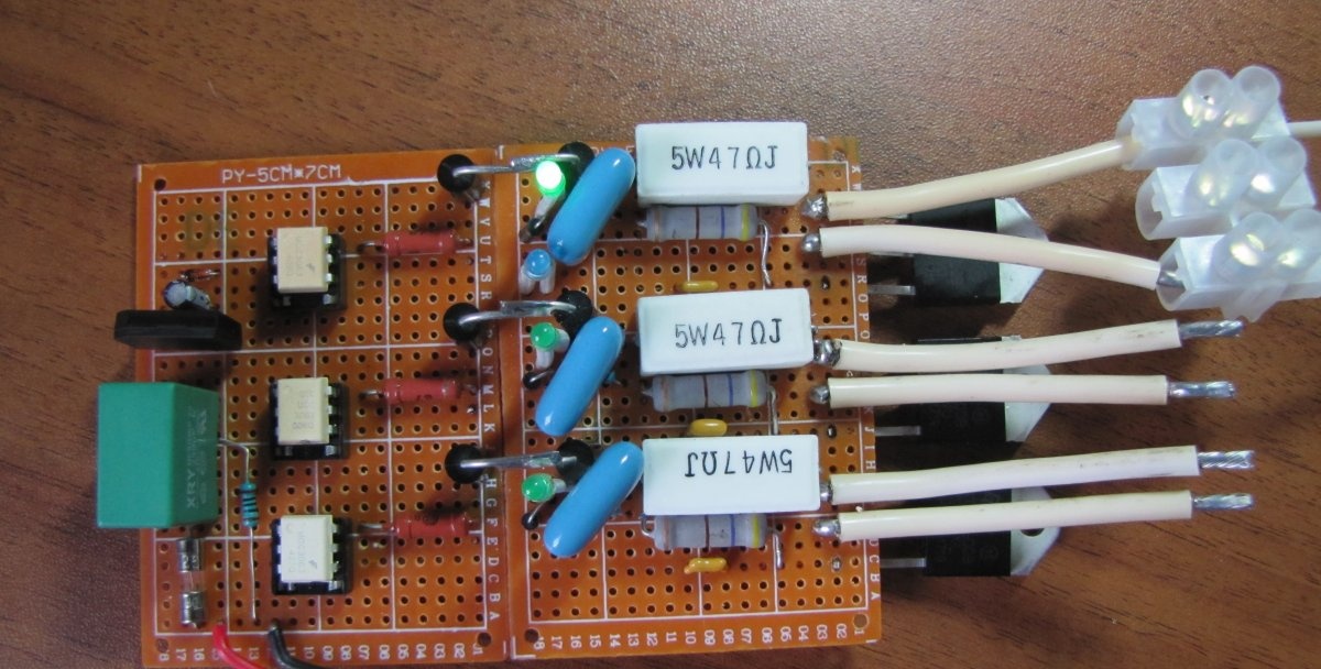
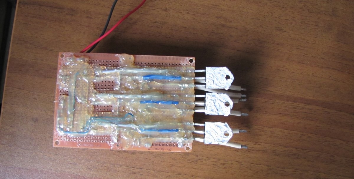
After making sure that the relay is working, fill the places on the board where there is high voltage with hot melt glue.
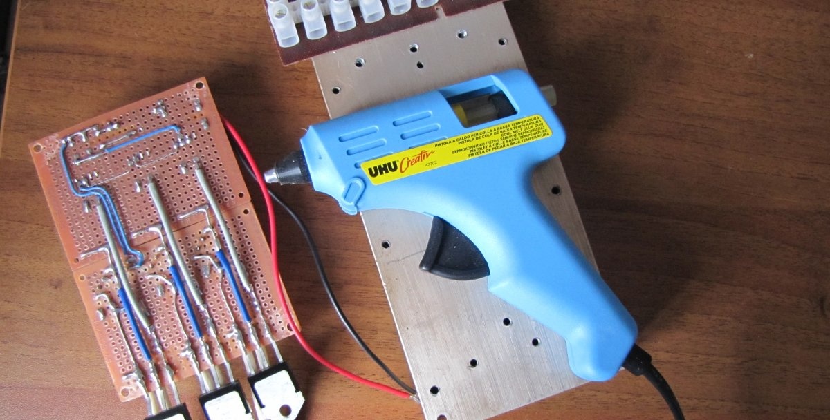
Lubricate the triacs with heat-conducting paste and attach them to the radiator. The breadboard is mounted on insulating washers.
We fix the device in the case and close it. The three-phase solid state relay is ready for use.
Watch the video
Watch the video for testing the relay in operation.