Do it yourself
Life hacks, master classes, useful tips, recipes.
home » Electronics » Simple circuits » The most reliable relay for turn signals

As you know, all modern cars are equipped with direction indicators, which are a flashing light on the left or right side of the body or Light-emitting diode. Sometimes a standard electromechanical relay fails, and getting a powerful automotive relay is not always so easy. Semiconductor devices come to the rescue - after all, building such a relay is powerful with just a couple of transistors.
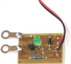
Relay circuit

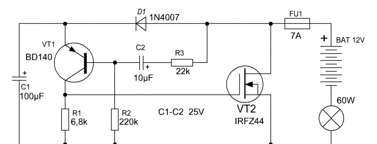
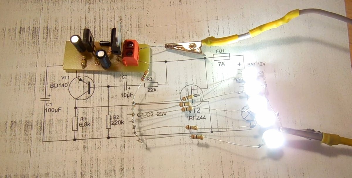
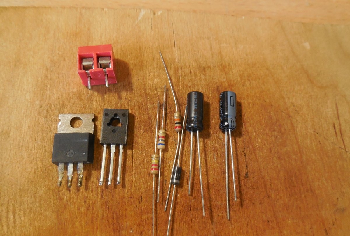
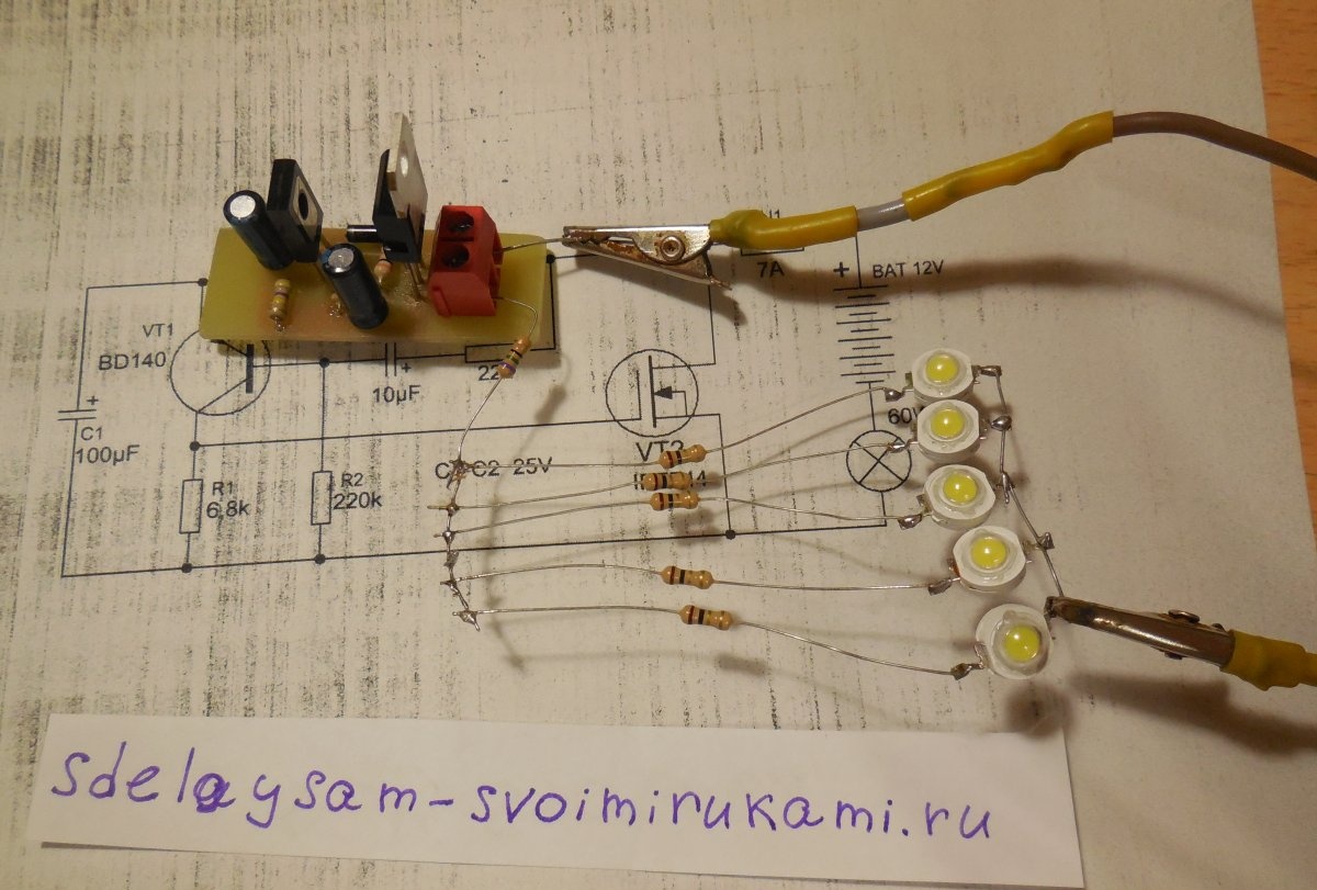
The circuit is an asymmetrical multivibrator; it is connected in an open circuit in series with the light bulb and the power source. When voltage is applied, the light immediately begins to blink. VT2 in the diagram is a field-effect transistor; it is through it that the entire light bulb current flows. It is preferable to use a transistor with the lowest possible open junction resistance. IRFZ44N, IRF740, IRF630 are suitable here. If you use it instead of a light bulb Light-emitting diode low power, you can use a bipolar transistor, for example, TIP122. Transistor VT1 of medium power p-n-p structure, BD140, KT814 are suitable. Diode D1 can be installed 1N4007 or 1N4148. The blinking frequency directly depends on the capacitance of the capacitors and the resistance of the resistors.To increase the frequency, you need to reduce the capacitance of capacitor C2, and to decrease the frequency, on the contrary, increase its capacitance. You can also experiment with the values ​​of other circuit elements and observe how the duty cycle of the pulses changes.
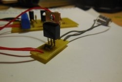
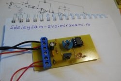
tranzistornoe-rele-dlja-povorotnikov.zip [97.21 Kb] (downloads: 1955)

Circuit assembly

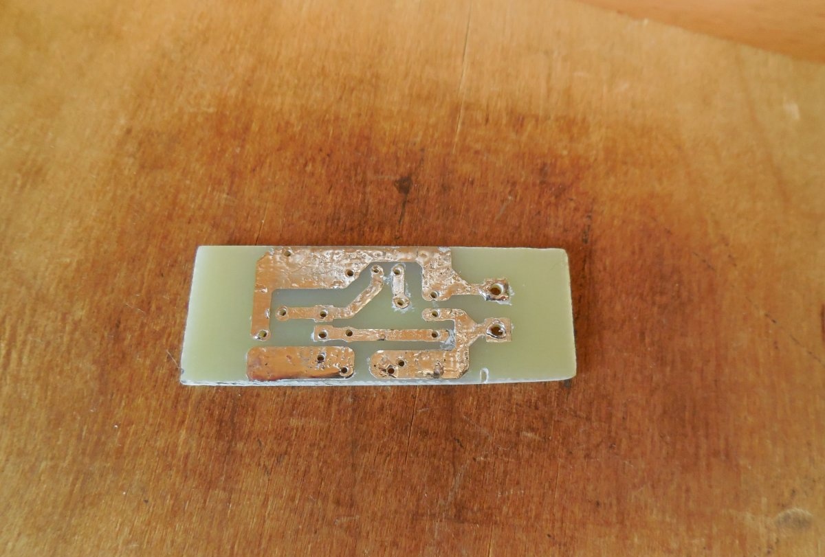
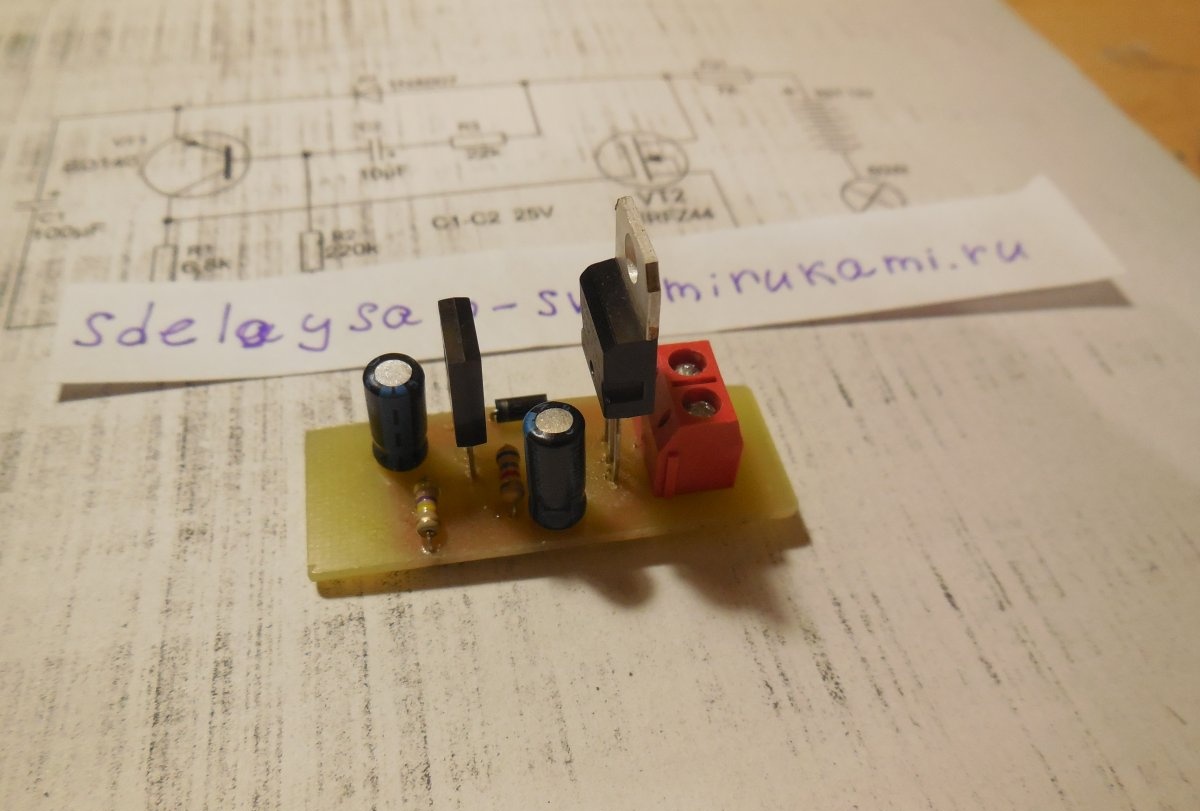
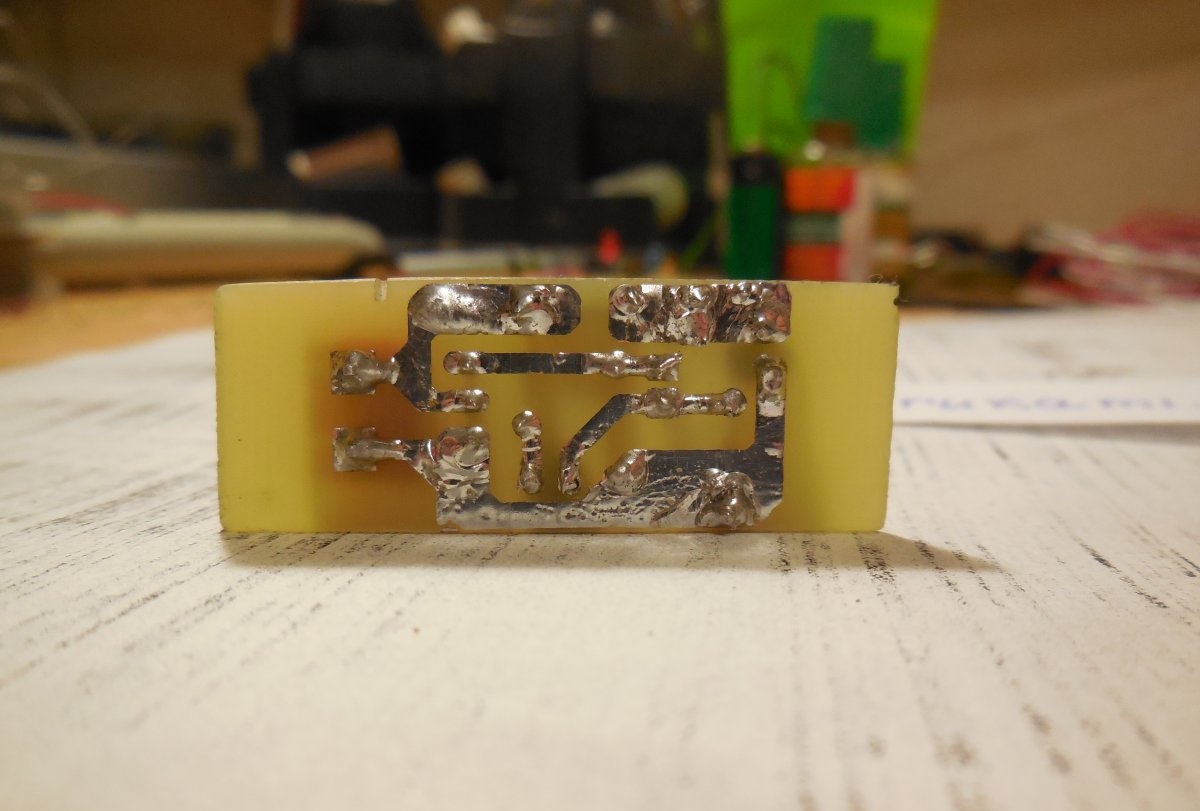
The entire circuit is assembled on a miniature printed circuit board measuring 35 x 20 mm; it can be manufactured using the LUT method. The tracks must be tinned after etching, then the copper will not oxidize.

First of all, resistors and a diode are soldered onto the board. After them, everything else is a pair of transistors, electrolytic capacitors and a terminal block. It is important not to confuse the pinout of the transistors and the polarity of the capacitors, otherwise the circuit will not work. When all the parts are soldered onto the board, be sure to wash off the remaining flux and check the correct installation.

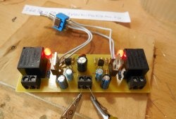
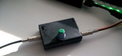
Setting up and testing turn signal relays

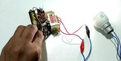
For testing, you can connect several powerful ones as a load. LEDs. We connect the negative of the load directly to the negative of the power supply, and connect the positive to the board. If a light bulb is used for testing, it can be connected with any polarity. We apply voltage and the light immediately begins to blink. The blinking frequency can be changed within a wide range, which is why this circuit can be found in many other applications besides being used as a turn signal relay. For example, you can use it to make a rear flashing light for a bicycle; you just need to increase the flash frequency by decreasing the capacitor capacity. The circuit can switch high power - up to several hundred watts, if you use a field-effect transistor designed for the appropriate current.With a power of more than 100 watts, it is advisable to install the transistor on a small radiator, otherwise it may heat up during long-term operation. This circuit, unlike a traditional electromechanical relay, has no moving parts, so it is much more durable if used with parts of the proper quality. If necessary, a fuse, indicated in the diagram as FU1, is also connected in series with the load. Happy assembly.

Watch the video

The video clearly demonstrates the operation of this circuit; several LEDs with resistors.

come back
Comment
  • bowtiesmilelaughingblushsmileyrelaxed relaxedsmirk
    heart_eyeskissing_heartkissing_closed_eyesflushedrelievedsatisfiedgrin
    winkstuck_out_tongue_winking_eyestuck_out_tongue_closed_eyesgrinningkissingstuck_out_tonguesleeping
    worriedfrowninganguishedopen_mouthgrimacingconfusedhushed
    expressionlessunamusedsweat_smilesweatdisappointed_relievedwearypassive
    disappointedconfoundedfearfulcold_sweatperseverecrysob
    joyastonishedscreamtired_faceangryragetriumph
    sleepyyummasksunglassesdizzy_faceimpsmiling_imp
    neutral_faceno_mouthinnocent
3+three=
Comments (10)
  1. Guest Vladimir
    #1 Guest Vladimir Guests 29 August 2018 16:53
    2
    This design cannot be used as turn signals - they blink too quickly
    signal-pause time GOST approved
  2. Guest Vlad
    #2 Guest Vlad Guests 29 August 2018 18:23
    1
    I'm more interested in the cooling fan relay for a soft start using a simpler diagram
  3. Alexander
    #3 Alexander Guests 30 August 2018 10:03
    6
    The turn relay controls left/right turns (i.e. you will need at least 2 such circuits), and also changes the blinking frequency when one of the light bulbs burns out (this is an express diagnostic for the driver).Well, let’s not forget that it is also responsible for the emergency lights (blinking all the lights). In this case, turns work when the ignition is on and the emergency lights are always on.
    In general, the correct turn signal relay is not just a “powerful car relay”.
    1. Guest Nikolay
      #4 Guest Nikolay Guests 2 June 2019 23:41
      7
      No need for two relays. The relay (one!) is not installed on left/right. The lamps are separate, but are placed in an open circuit in the common wire +12 volts, which then goes to the turn switch and to the emergency lights, ensuring their cyclic operation.
      Those. the circuit is +12v. goes first to the turn relay, and from there to the emergency lights and turn switch, which connect the necessary lamps to the working relay.
  4. Guest Alexander
    #5 Guest Alexander Guests 5 October 2018 08:46
    4
    It will not work on a car, since a current relay is used when turning.
  5. Guest Vlad
    #6 Guest Vlad Guests January 12, 2019 09:07
    4
    A field-effect transistor of this polarity in this circuit will only work normally with LEDs! With powerful lamps it will get very hot, because the source must be at negative and the lamp is connected to the drain circuit. Or the gate opening voltage should be 3-4 volts higher than the supply voltage. Learn materiel...
  6. Guest Oleg
    #7 Guest Oleg Guests 17 May 2019 16:21
    1
    Today I soldered this circuit - it started working right away!))) Instead of VT1, I soldered MPSA92, and the field switch IRFP260NPBF. Capacitors and resistors according to the diagram. Before this there was a circuit with a blinking LED, but for some time now it began to fail. I was looking on the Internet for a more reliable scheme and found this one. Thank you!
  7. mountains
    #8 mountains Guests December 27, 2019 19:40
    2
    It’s better to do it on KT315. and the frequency is not difficult to choose. and there are only three parts in the diagram. capacitor resistor and KT315.
  8. Name
    #9 Name Guests 28 September 2020 15:54
    3
    Why is the lamp where it is? Why not between the drain and the node after the fuse?
  9. Guest Evgeniy
    #10 Guest Evgeniy Guests 10 November 2020 04:44
    0
    If R-2 is replaced with 100 kOhm and if you plan to use LEDs Then install an additional 7-10 kOhm resistor in parallel with the LEDs (bypass them), then everything works fine.

Now you can at least hang a horizontal bar on drywall

New Year's decoupage of champagne bottle | Do it yourself

Cold smoke generator for cold smoking

Simple inverter 12V – 220V 50Hz | Do it yourself

«Do it yourself - with your own hands» - a site of interesting homemade products made from scrap materials and items at home. Step-by-step master classes with photos and descriptions, technologies, life hacks - everything a real master or just a craftsman needs for needlework. Crafts of any complexity, a large selection of directions and ideas for creativity.

We recommend reading

Washing machine error codes