Many sound-reproducing devices, whether tape recorders or amplifiers of the end of the last century, were equipped with a dial indicator on the front panel. Its hand moved to the beat of the music, and although it had no practical meaning, it looked very beautiful. Modern equipment, in which compactness and high functionality come first, no longer has such luxury as a dial indicator for sound. However, it is now quite possible to find a pointer head, which means that such an indicator can be easily assembled with your own hands.
Scheme
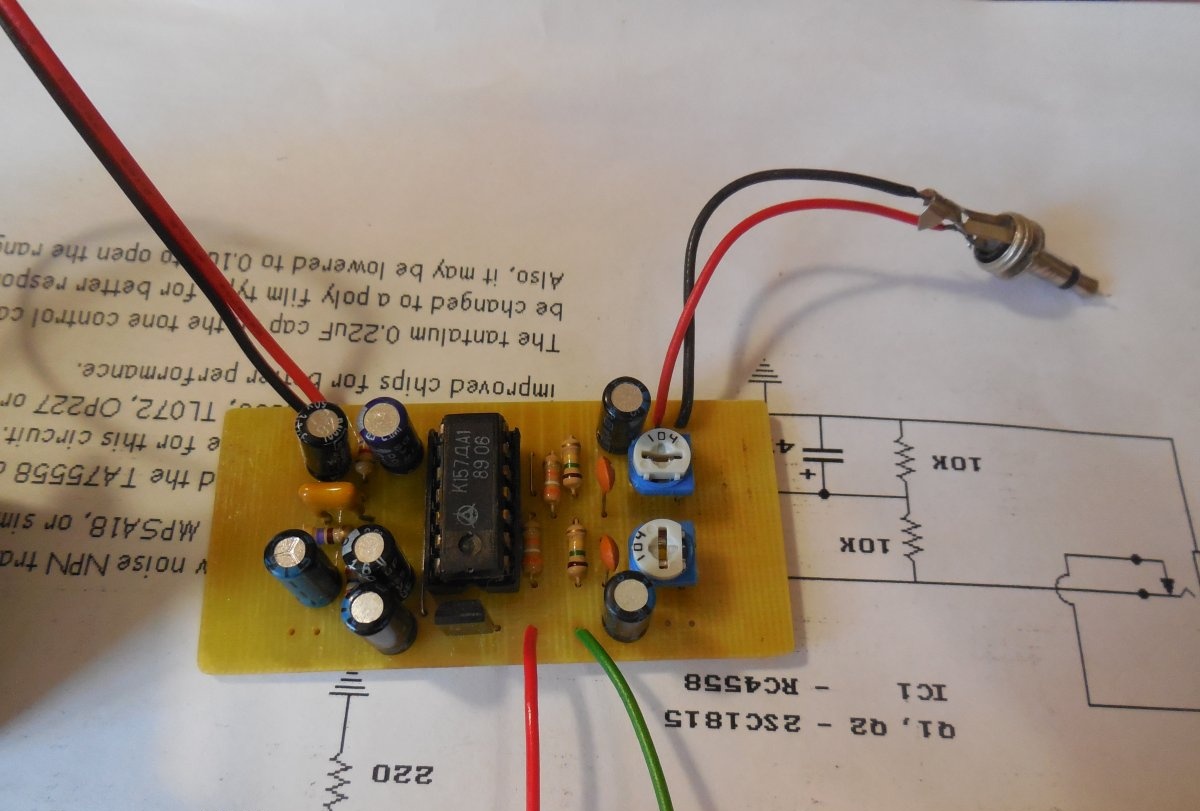
Its basis is the Soviet K157DA1 microcircuit, a two-channel full-wave average signal rectifier. The supply voltage of the circuit lies in a wide voltage range, from 12 to 16 volts, because the circuit contains a 9 volt stabilizer (VR1 in the diagram). If you use a stabilizer in a metal case TO-220, then the voltage can be supplied up to 30 volts. Trimmer resistors R1 and R2 regulate the signal level at the input of the microcircuit. The circuit is not critical to the ratings of the components used.You can experiment with the capacitances of capacitors C9, C10, which affect the smooth movement of the needle, as well as with resistors R7 and R8, which set the return time of the needle. In L and In R in the diagram are connected to a sound source, which can be any device with a linear output - be it a computer, player or telephone.
Circuit assembly
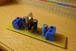
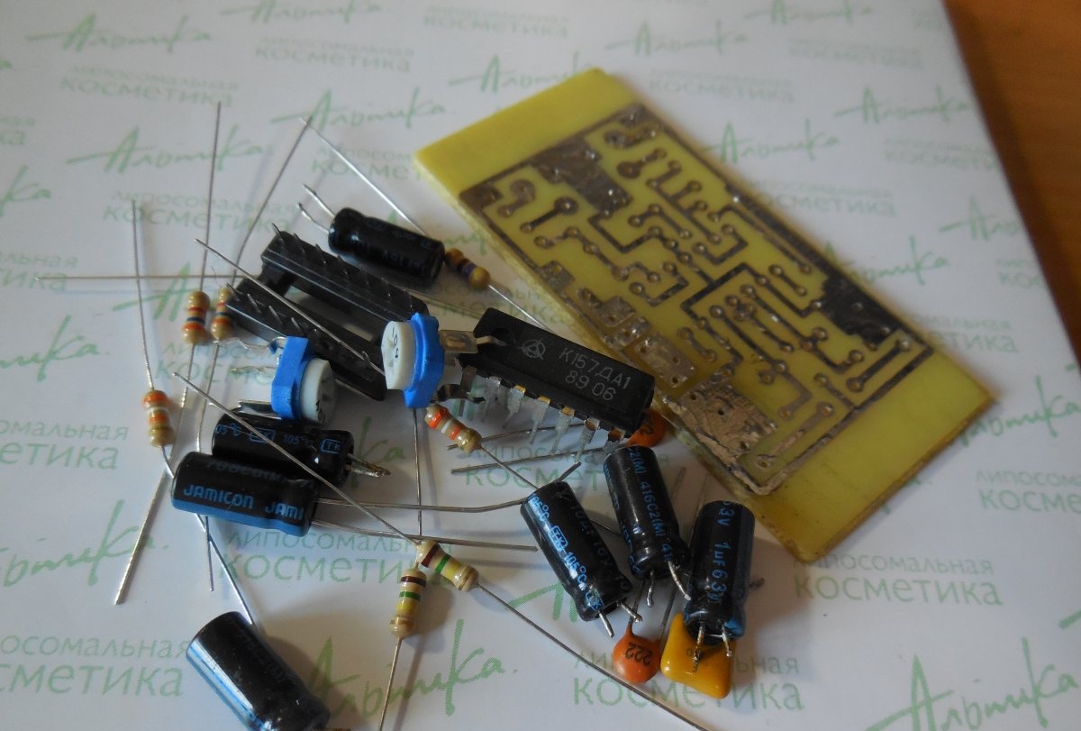
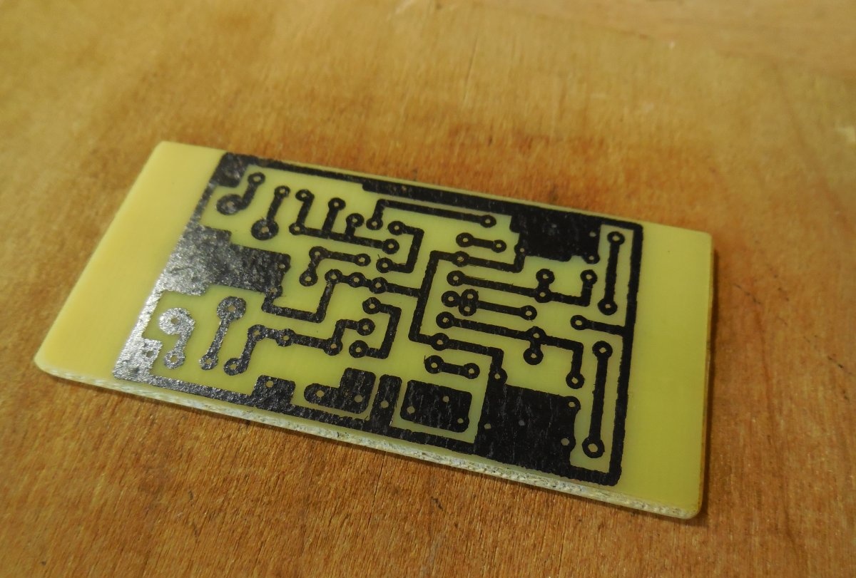
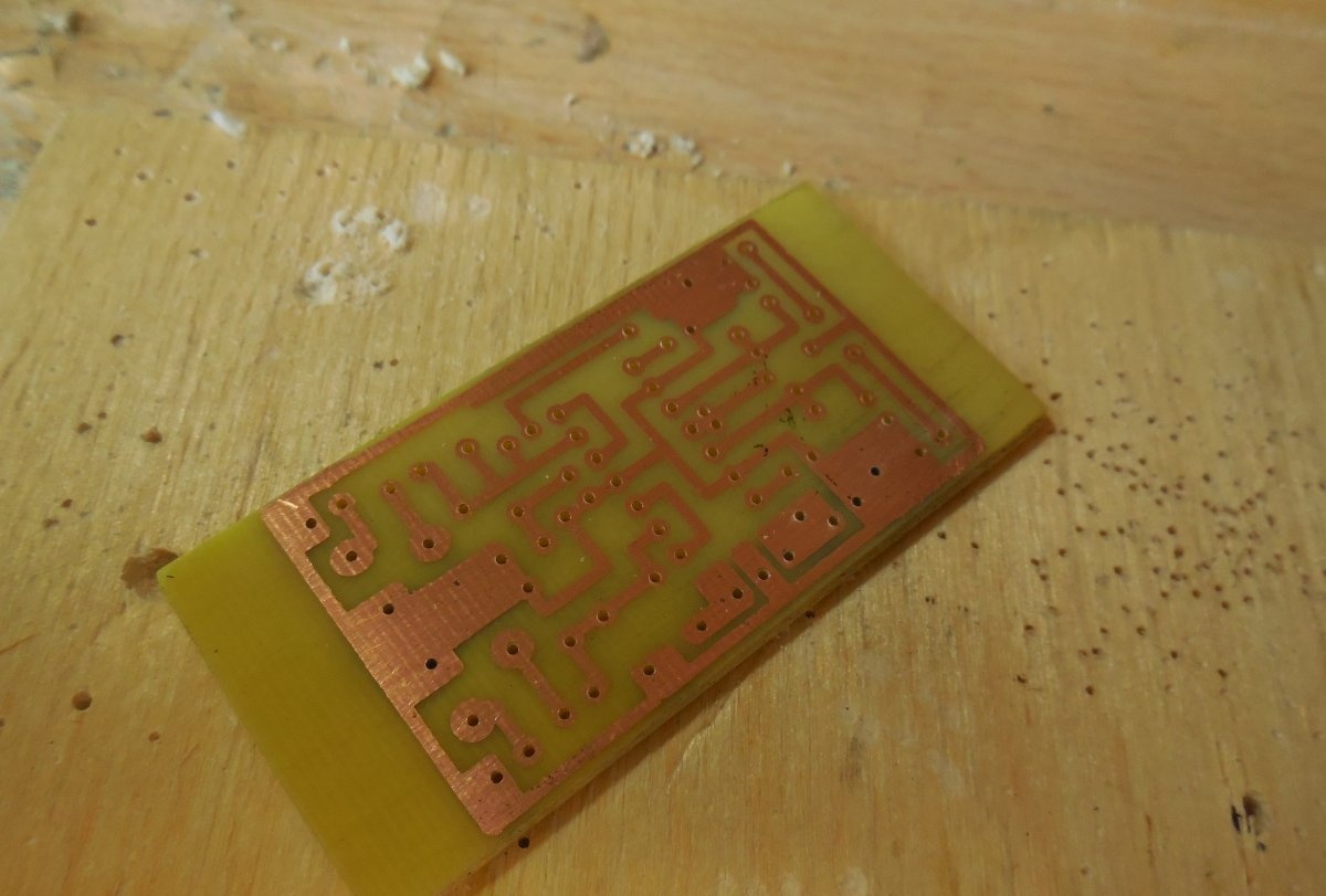
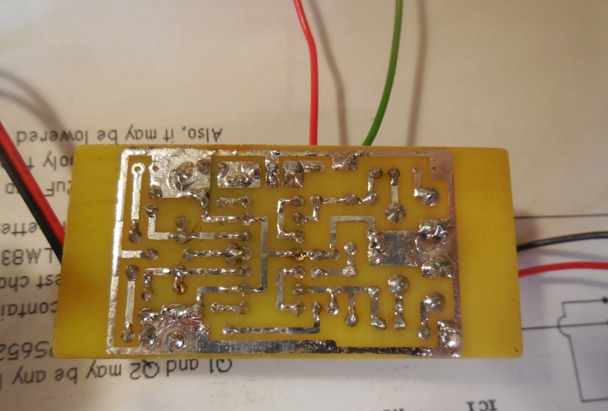
The indicator board is manufactured using the LUT method on a piece of textolite measuring 30 x 50 mm. Just in case, the microcircuit should be installed in the socket, then it can be replaced at any time. After etching, the board must be tinned, then it will look beautiful from the side of the tracks, and the copper itself will not oxidize. First of all, small parts are sealed - resistors, ceramic capacitors, and only then electrolytic capacitors, trimming resistors, and a microcircuit. Lastly, all connecting wires are soldered. The board contains two channels at once and involves the use of two arrow heads - for the right and left channel, however, you can use one arrow head, then the input and output contacts for the other channel on the board can simply be left empty, as I did. After installing all the parts on the board, be sure to wash off all remaining flux and check adjacent tracks for short circuits. To connect the board to the signal source, it is most convenient to use a 3.5 jack plug. In this case, if the length of the wires from the board is large (more than 15 cm), a shielded wire should be used.
arrow head
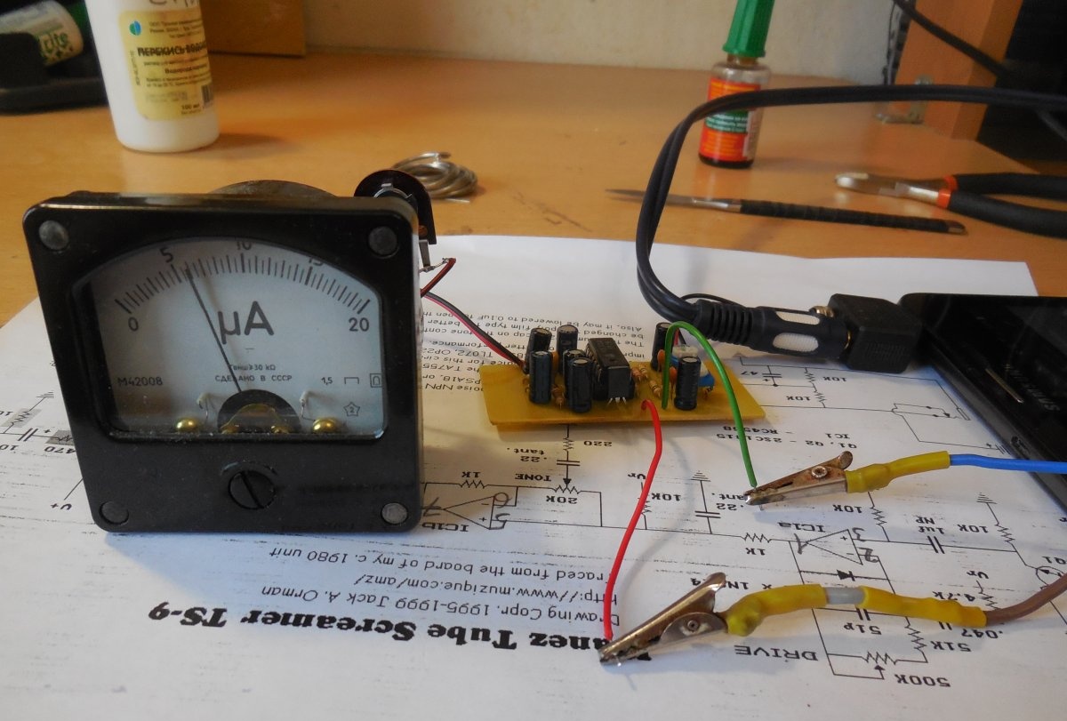
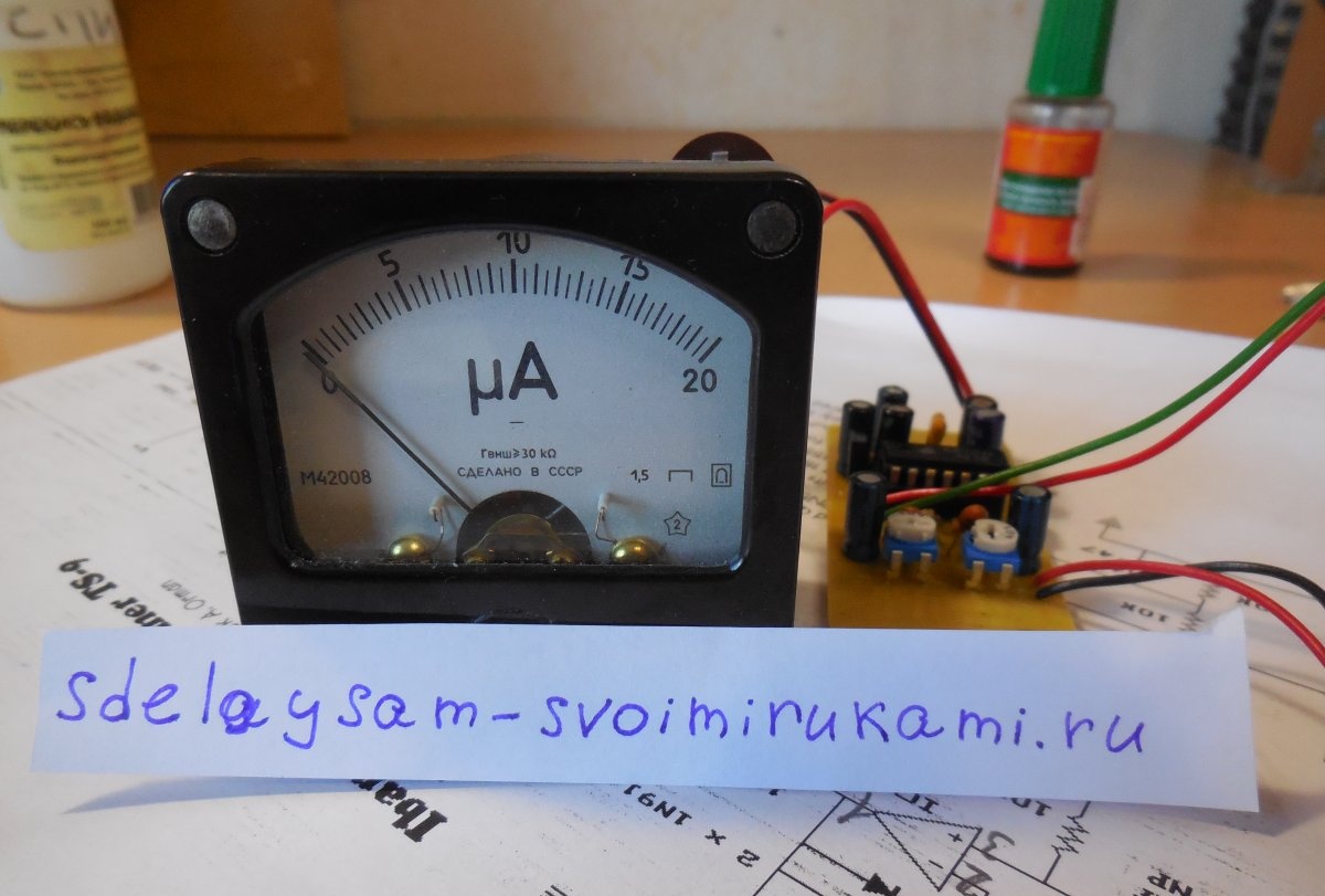
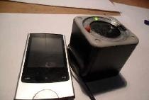
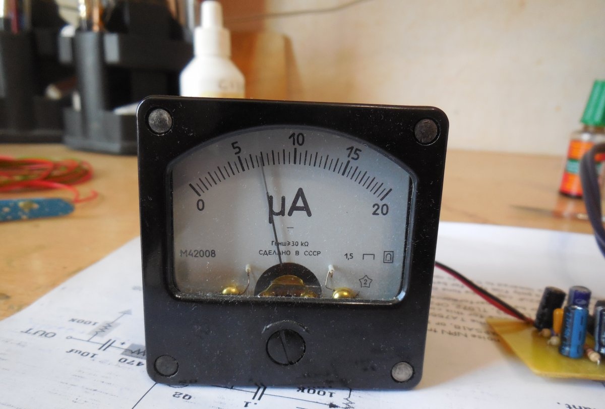
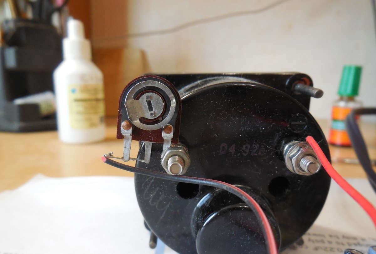
Finding Soviet pointer heads on sale now is not difficult; there are many types of them, in different shapes and sizes.I used a small M42008 pointer head, it doesn't take up much space and looks nice. Any head with a total deflection current of 10-100 microamps is suitable for this circuit. To complete the picture, you can also replace the native scale, calibrated in microamps, with a special sound scale, calibrated in decibels. However, you need to connect the pointer head to the circuit not directly, but through a trimming resistor with a nominal value of 1-2 megaohms. Its middle contact is connected to any of the outer ones and connected to the board, and the remaining contact is connected directly to the head, as can be seen in the photo below.
Setting up the indicator
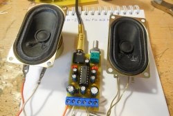
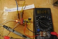
When the board is assembled, the pointer head is connected, you can begin testing. First of all, by applying power to the board, check the voltage at pin 11 of the microcircuit, there should be 9 volts. If the supply voltage is normal, you can apply a signal from a sound source to the board input. Then, using resistors R1 and R2 on the board and a trimming resistor at the pointer head, achieve the required sensitivity so that the pointer does not go off scale, but is approximately in the middle of the scale. This completes the basic setting, the arrow will move smoothly to the beat of the music. If you want to achieve sharper arrow behavior, you can install resistors with a resistance of 330-500 Ohms parallel to the arrow heads. Such an indicator will look great in the housing of a homemade amplifier, or as an independent device, especially if you illuminate the indicator with a pair of LEDs. Happy building!