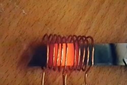
An induction heater allows you to heat metal until it turns red without even touching it. The basis of such a heater is a coil in which a high-frequency field is created, which acts on a metal object placed inside. A high density current is induced in the metal, which causes the metal to heat up. Thus, to create an induction heater you will need a circuit that generates high-frequency oscillations and the coil itself.
Scheme
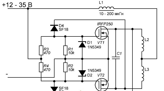
Above is a diagram of a universal ZVS driver, which is based on powerful field-effect transistors. It is best to use IRFP260, rated for a current of more than 40 A, but if you cannot get these, you can use IRFP250, they are also suitable for this circuit. D1 and D2 are zener diodes, you can use any voltage from 12 to 16 volts. D3 and D4, ultra-fast diodes, can be used, for example, SF18 or UF4007. It is advisable to take resistors R3 and R4 with a power of 3-5 watts, otherwise they may heat up. L1 – inductor, can be taken in the range of 10-200 µH. It must be wound with a sufficiently thick copper wire, otherwise heating cannot be avoided.Making it yourself is very simple - just wind 20-30 turns of wire with a cross-section of 0.7-1 mm on any ferrite ring. Particular attention should be paid to capacitor C1 - it must be designed for a voltage of at least 250 volts. Capacitance can vary from 0.250 to 1 µF. A large current will flow through this capacitor, so it must be massive, otherwise it will heat up. L2 and L3 are the same coil inside which the heated object is placed. It consists of 6-10 turns of thick copper wire on a mandrel with a diameter of 2-3 centimeters. You need to make a tap on the coil from the middle and connect it to coil L1.
Heater circuit assembly
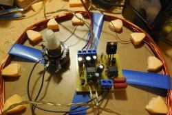
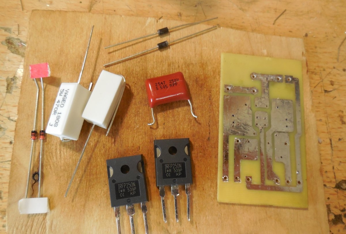
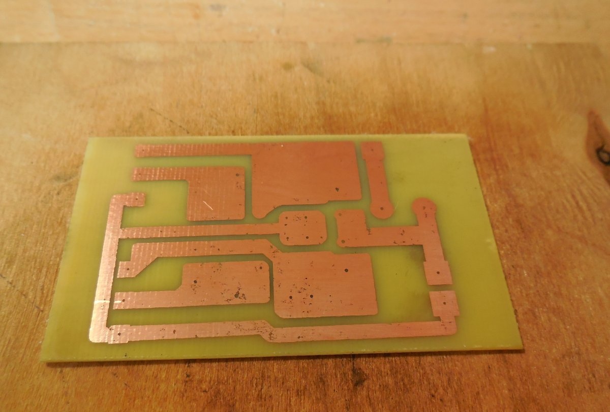
The circuit is assembled on a piece of PCB measuring 60x40 mm. The printed circuit board design is completely ready for printing and does not need to be mirrored. The board is made using the LUT method; below are several photographs of the process.
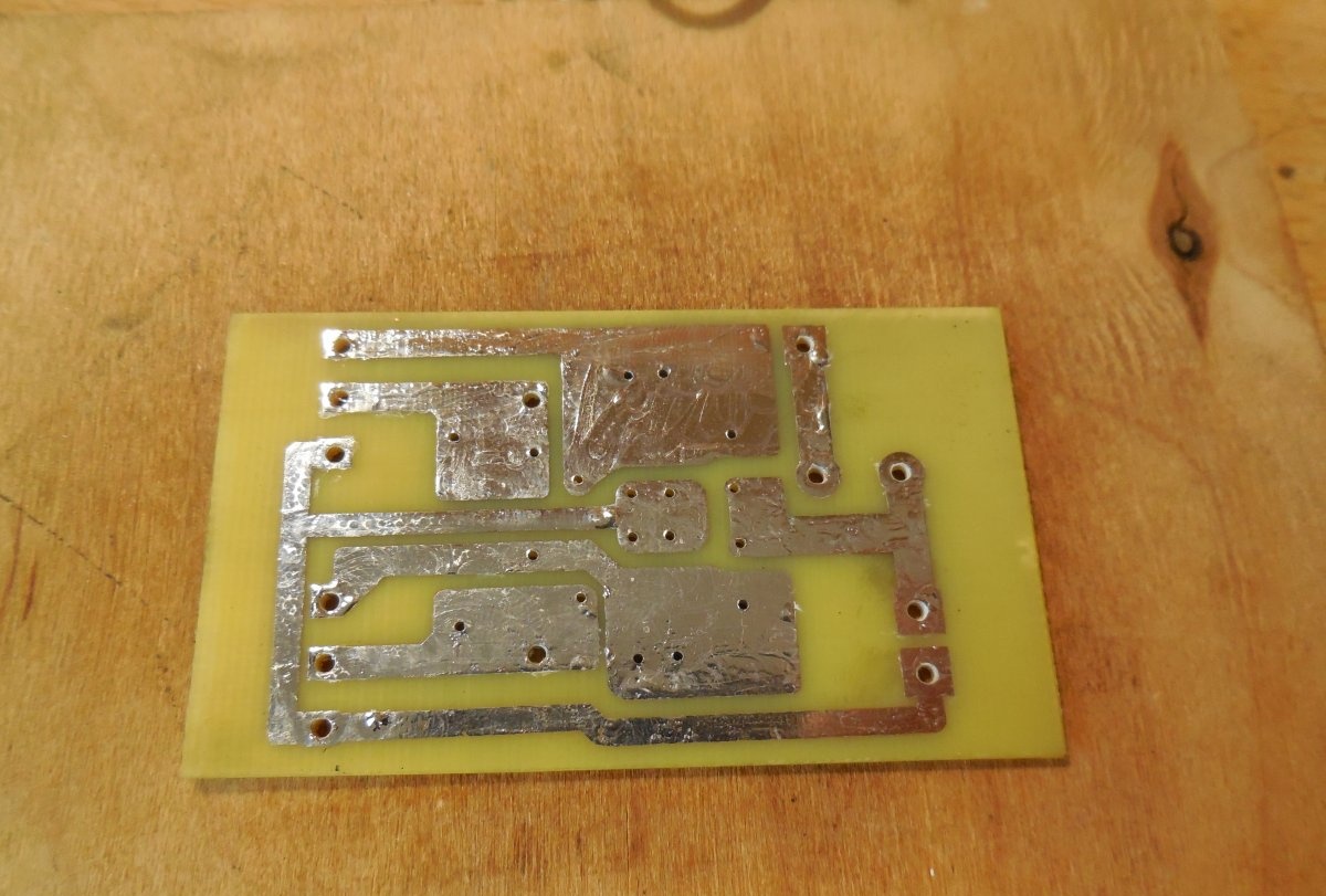
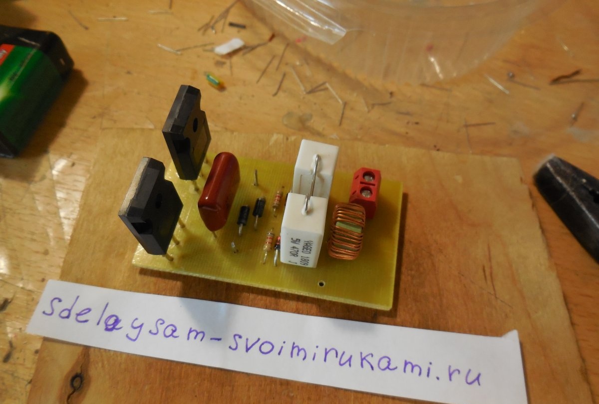
After drilling the holes, the board must be tinned with a thick layer of solder for better conductivity of the tracks, because large currents will flow through them. As usual, small parts, diodes, zener diodes and 10 kOhm resistors are soldered first. Powerful 470 Ohm resistors are installed on the board while standing to save space. To connect the power wires, you can use a terminal block; there is a place for it on the board. After soldering all the parts, you need to wash off the remaining flux and check the adjacent tracks for short circuits.
Making an induction coil
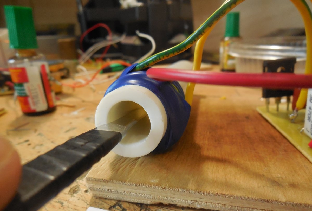
The coil consists of 6-10 turns of thick copper wire on a mandrel with a diameter of 2-3 centimeters; the mandrel must be dielectric. If the wire holds its shape well, you can do without it altogether.I used regular 1.5mm wire and wound it around a piece of plastic pipe. Electrical tape works well for fastening the turns.
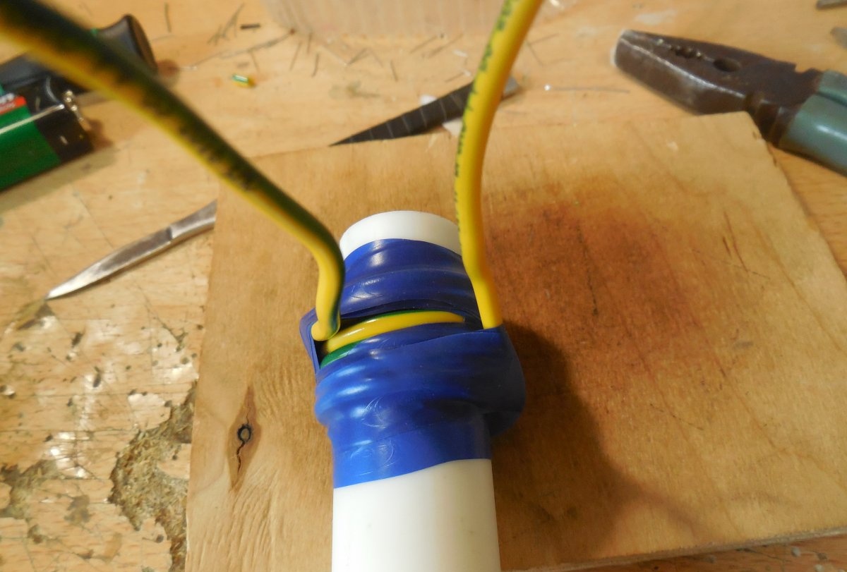
A tap is made from the middle of the coil; you can simply remove the insulation from the wire and solder a third wire there, as I did. All wires must have a large cross-section to avoid unnecessary losses.
First launch and testing of the heater
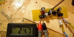
The supply voltage of the circuit is in the range of 12-35 volts. The higher the voltage, the more the metal object heats up. But at the same time, the heat dissipation on the transistors increases - if with a power supply of 12 volts they hardly heat up, then at 30 volts they may already require a radiator with active cooling. You should also monitor capacitor C1 - if it heats up noticeably, then you should take a higher voltage one, or assemble a battery of several capacitors. When starting up for the first time, you will need an ammeter connected to the break in one of the supply wires. At idle, i.e. With no metal object inside the coil, the circuit draws about 0.5 amps. If the current is normal, you can place a metal object inside the coil and watch it heat up literally before your eyes. Happy assembly.