There are many different LED flasher circuits on the Internet - simple, complex, with or without microcircuits. But a regular flashing LED will no longer surprise anyone, so there is a need to assemble something more advanced. For example, an acoustic flasher - a microphone picks up sound and turns it into flashes LEDs. The diagram is presented below.
Scheme
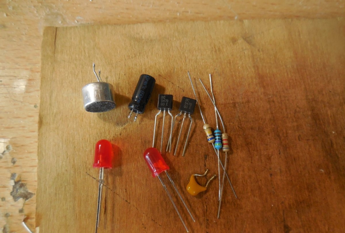
The diagram shows an electret microphone, which converts sound vibrations into electrical ones. You can find it in broken telephone headsets or in a radio parts store. Transistors T1 and T2 amplify the signal so that it is enough to ignite LEDs. You can use almost any low-power n-p-n transistors, for example, BC547, KT315, KT3102. LEDs ordinary 3-volt ones of any color are used, you can put two pieces, as indicated in the diagram, or more. Capacitor C1 serves to suppress power ripple; its capacitance can range from 10-100 μF. The circuit supply voltage is from 3 to 5 volts.
Flasher assembly
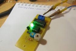
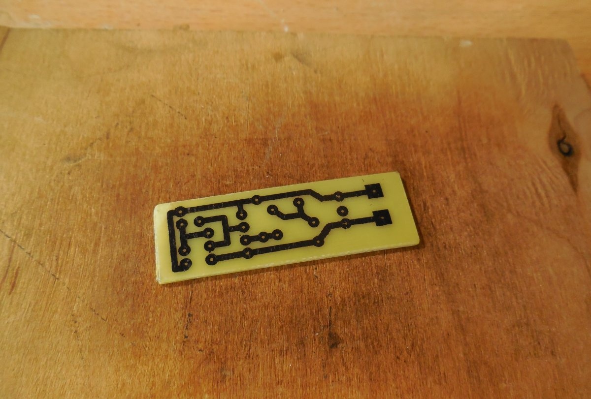
The circuit is assembled on a miniature printed circuit board measuring 45 x 15 mm, which can be made using the LUT method. The printed circuit board is completely ready for printing; there is no need to mirror it. Please note that the board is designed to install BC547 transistors; if you use similar transistors with a different pinout, you will have to swap their pins on the board. Below are some photos of the board making process.
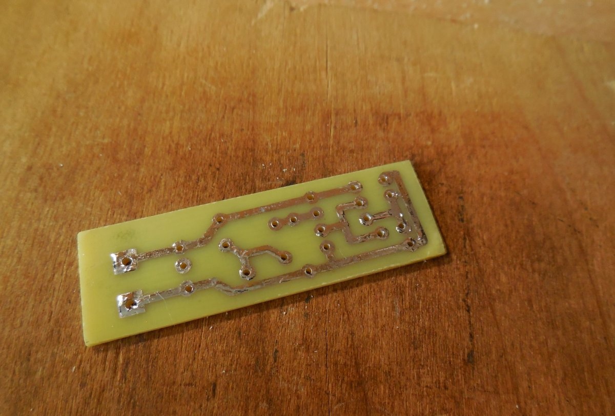
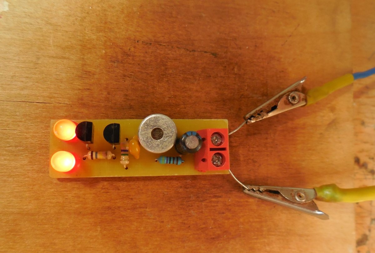
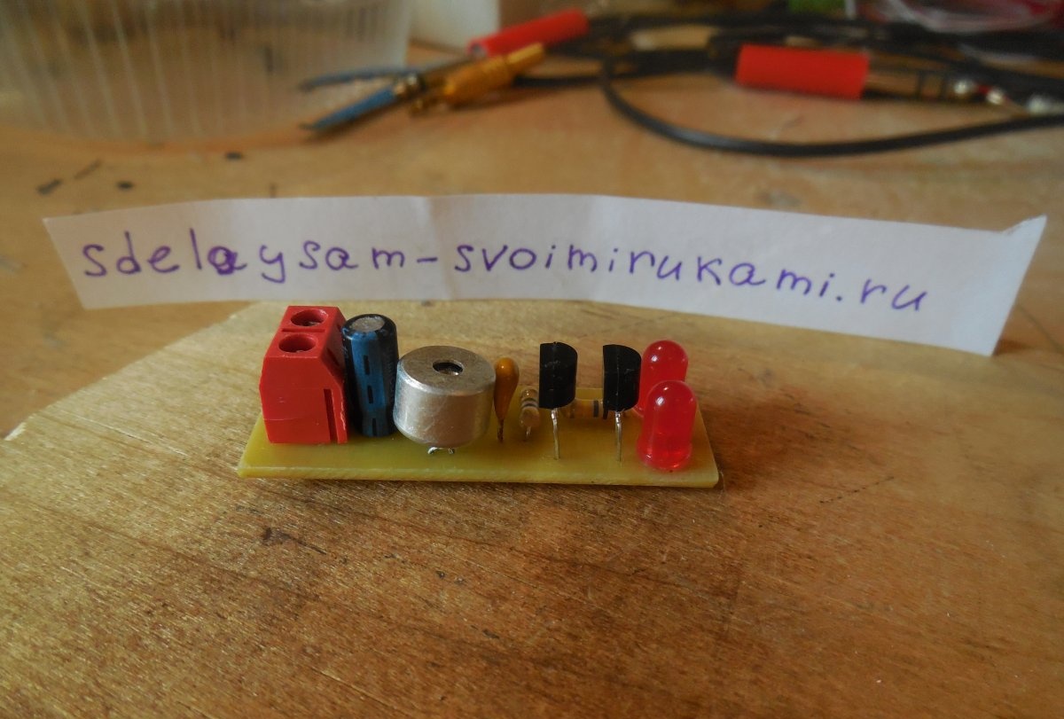
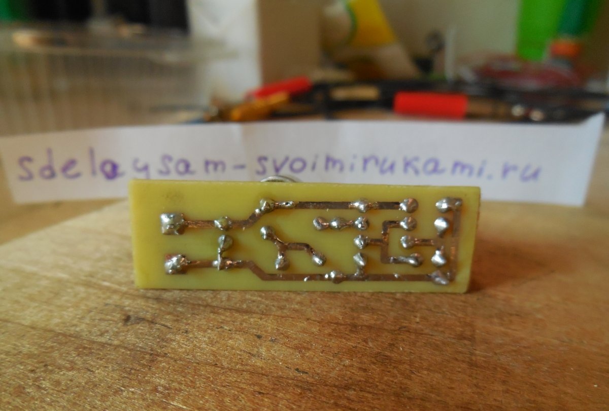
It is advisable to tin the tracks, this will protect the copper from oxidation and make further soldering of parts easier. First of all, small parts are installed on the board - resistors, transistors, and only then capacitors and LEDs. It is most convenient to use a screw terminal block to connect the power wires. When installing a microphone, be sure to observe its polarity - the negative leg of the microphone is connected to its metal body, it must be soldered to the negative circuit. After completing the assembly, you need to wash off the remaining flux from the board and check the correct installation.
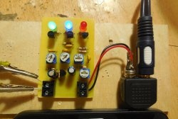
Setup and testing
We supply power to the board and watch the reaction LEDs – they must be completely extinguished in the absence of sound. If the LEDs glow continuously, then you need to increase the resistance of resistors R2 and R3 by 1.5 - 2 times until the LEDs go out, this is the only adjustment of the circuit. After this, the LEDs will instantly flash if any sound, clap, click or even music is heard nearby. When using a sensitive microphone, the sound detection range is approximately 6-7 meters. The circuit will be a great toy for children - after all, watching how the LEDs light up at the slightest sound is quite exciting.The circuit can also be used to test the sensitivity of electret microphones. Happy assembly.