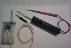
To work you will need:
- soldering iron with a thin tip;
- low-melting solder;
- copper wire coated with varnish insulation (PEV, PEV-2 or similar). For power buses, you will need a wire with a diameter of about 1 mm, and when choosing a wire for inter-element installation, you should be guided by the ability to easily give it the required shape;
- DC source with voltage 5÷15V;
- tweezers and scissors or nippers;
- a small piece of plastic for the clip under LEDs and a drill with a drill bit. The drill size must be equal to the diameter of the emitter LED.
Parts used:
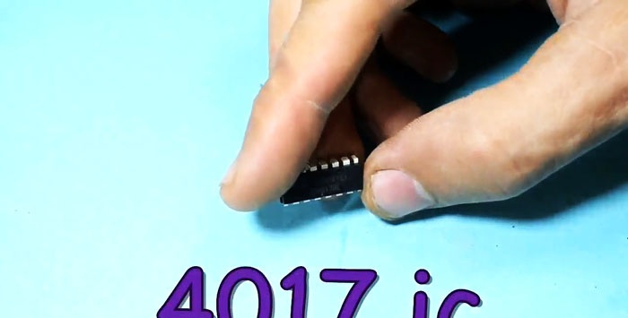
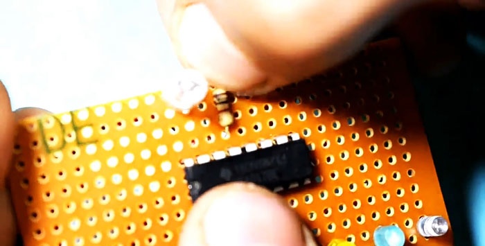
- chip CD4017.
- two resistors with a resistance of 330 ÷ 470 Ohms;
- 10 regular LEDs to indicate the signal level at the decoder outputs;

- 1 x L-314 series Blinking LEDs or equivalent. This is a relatively new type LEDs, containing a radiating element and a control circuit for its operation. As a rule, its markings contain the letter “B” after the numbers. In this design, it performs the function of a control pulse generator.
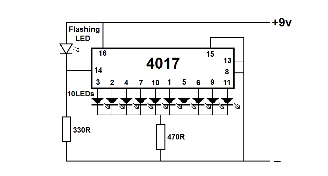
For ease of assembly, let us recall the pinout of the microcircuit and LEDs.
Assembly sequence:
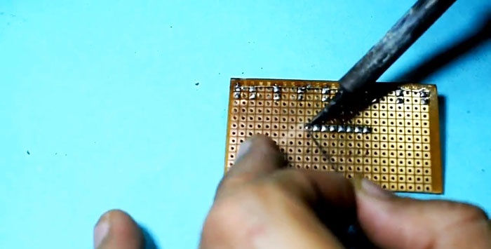
1. We make a holder for LEDs using technology available to you. It is important to note that all holes should be drilled before the plate is given its final dimensions. In this case, it will be more convenient to mark the centers of the holes and the risk of breakage during drilling and stripping will be minimal;
2. We form the leads of the signal LEDs, bending them in opposite directions;
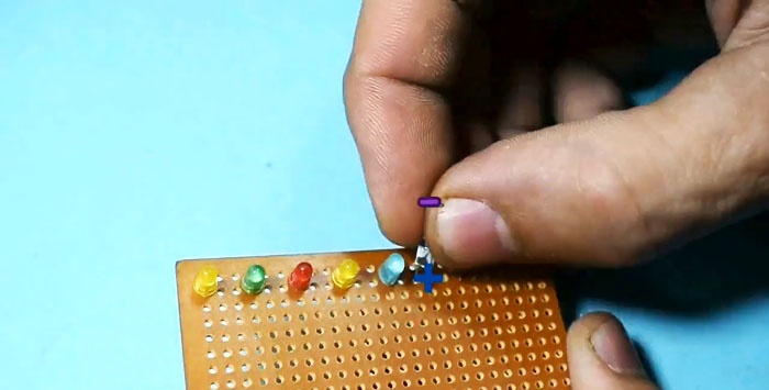
3. Install all 10 LEDs into the holes on the pre-made holder. It is important to maintain polarity so that the anodes and cathodes are positioned uniformly;
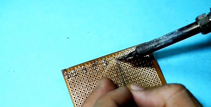
4. We tin a piece of thick copper wire in a section with a length equal to the length of the clip;
5. Solder all the LED cathodes to it. It is important here not to overheat the soldering areas. You can use tweezers on the LED side as a heat sink during soldering;
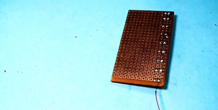
6. Using scissors or wire cutters, cut off the unused parts of the LED leads. This completes the assembly of the ten-element indicator, which we will now connect to the decoder chip;
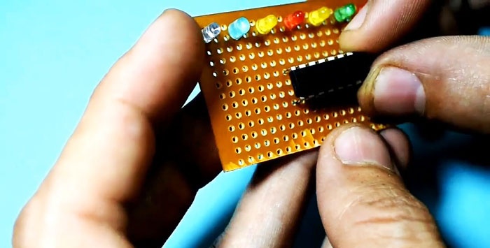
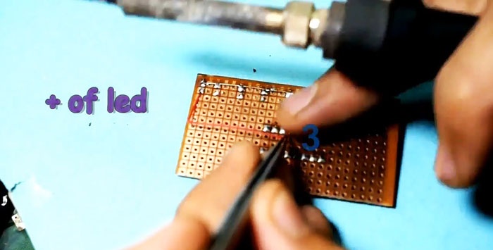
7. Cut a piece of thin copper wire measuring 4-5 cm and tin both ends to a length of 3-5 mm. Pre-tinning will speed up soldering and prevent overheating of the LED and microcircuit during the installation process;
8. Solder this conductor to the anode of the outer LED of the indicator, and then to the third pin of the microcircuit. Thus, we connect the Q0 pin of the chip to the anode of the first LED;
9. Now we have a more or less rigid connection between the microcircuit and the holder with LEDs, which makes subsequent installation much easier;
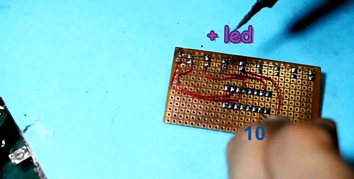
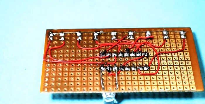
10. We make serial connections using pieces of insulated wire of the appropriate length:
- pin 2 (Q1) – anode 2 of the indicator LED;
- pin 4 (Q2) – anode 3;
- pin 7 (Q3) – anode 4;
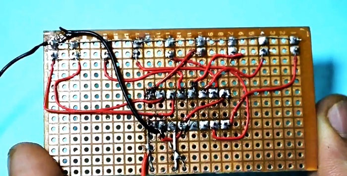
11. We bend it inside the case and solder pins 8, 13 and 15 of the microcircuit with a pre-tinned thick wire, which will serve as a negative power bus. It should protrude beyond the chip body by about 5-8 cm for convenient connection to the power source;
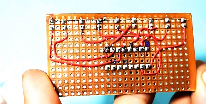
12. We connect with insulated conductors, bending them so that they do not touch each other:
- pin 1 (Q5) – anode 6;
- pin 5 (Q6) – anode 7;
- pin 6 (Q7) – anode 8;
- pin 10 (Q4) – anode 5;
- pin 9 (Q8) – anode 9;
- pin 11 (Q9) – anode 10;
13. Solder a flashing LED between pins 16 and 14 of the microcircuit, observing the polarity: anode to pin 16, and cathode to pin 14;
14. We use the LED leg soldered to the 16th pin of the microcircuit as a place to solder the positive power bus. Here we solder a piece of thick copper wire;
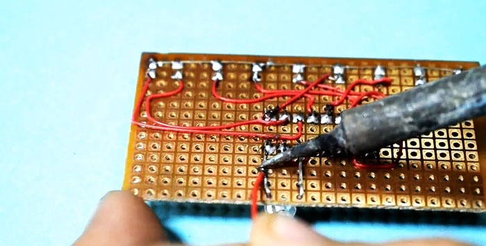
15. Between the wire bus connecting all the cathodes of the indicator LEDs and the negative power bus connecting pins 8, 13, 15 of the microcircuit, solder a 470 Ohm resistor;
16. Solder a 330 Ohm resistor between pin 14 of the microcircuit and the negative bus;
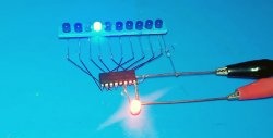
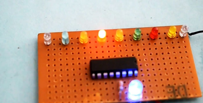
17. We check the assembled structure for absence of short circuits and supply power to the circuit.
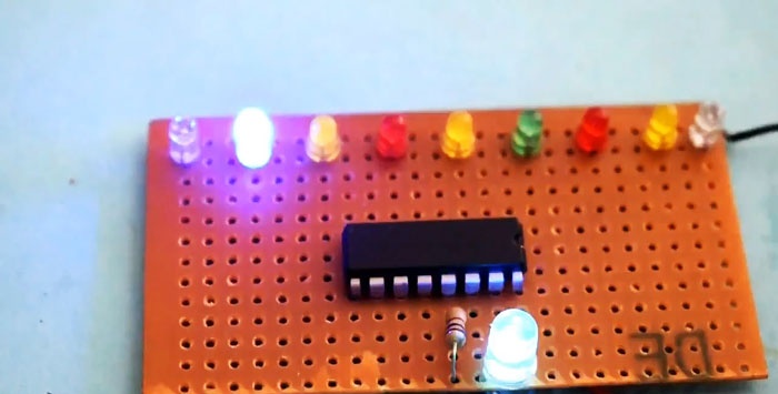
Conclusion
The described model allows you to visually study the operation of the decoder counter, but does not fully reveal all its capabilities. The load resistor values do not affect the operation of the circuit and can be changed.The suggested assembly sequence can be changed at your discretion.