Do it yourself
Life hacks, master classes, useful tips, recipes.
home » Electronics » DIY electronics » Simple hidden wiring detector in 15 minutes
Simple hidden wiring detector in 15 minutes

There is a strong and urgent need to drill a hole in the wall for a dowel. How can you avoid getting caught in passing wiring? In theory, you need to run to the store and buy an expensive tool to identify hidden wiring. It's good if it's available, but what if it's not? For example, in a provincial village you won’t find it during the day with fire.
Fortunately, such a device is easy to make yourself even if you have the basics of electronics.

Will need


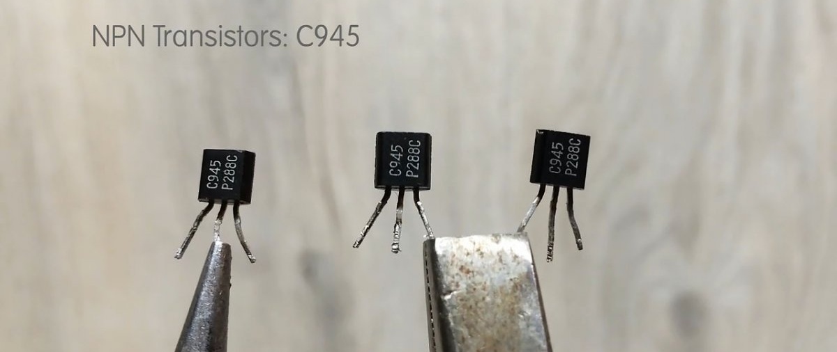
  • Transistor n-p-n structure. Almost anyone will do. The example uses C945.
    Simple hidden wiring detector in 15 minutes

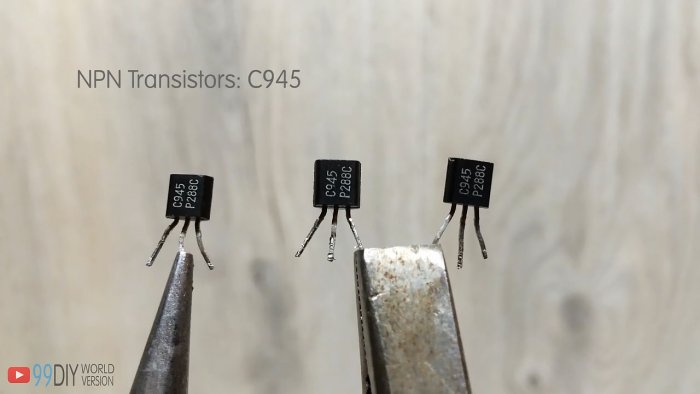
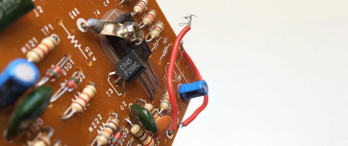
    There are a lot of these on old boards.
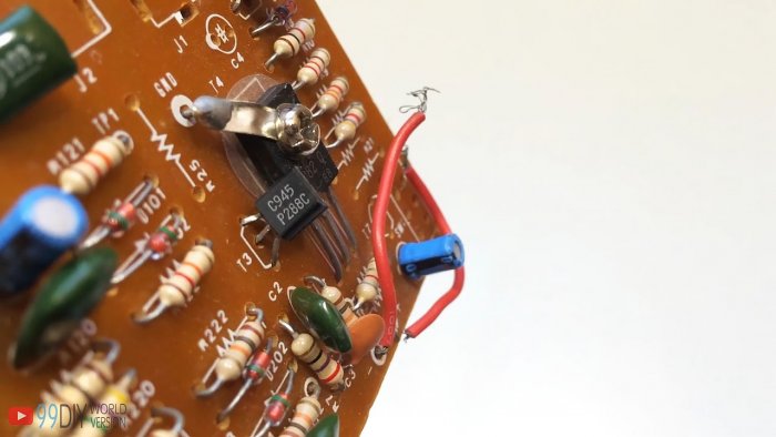
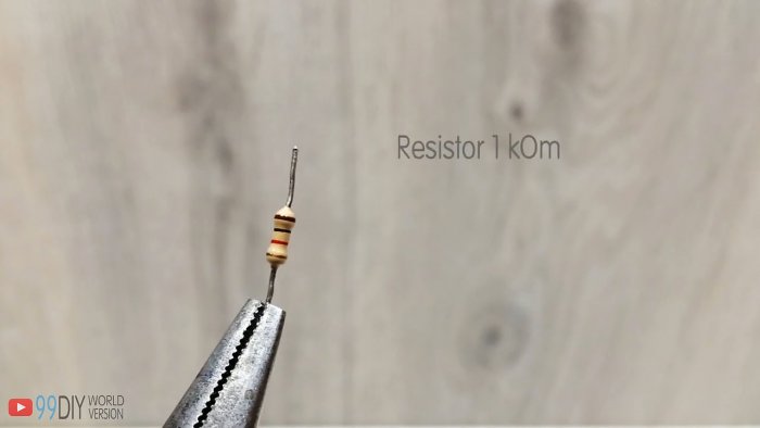
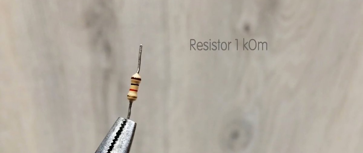
    Simple hidden wiring detector in 15 minutes

  • 1 kOhm resistor.
    Simple hidden wiring detector in 15 minutes

  • Light-emitting diode.
  • Connection block.
    Simple hidden wiring detector in 15 minutes

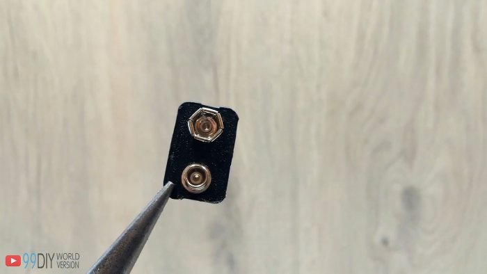
  • Battery 9 V, Krona type.
  • Copper wire 0.5-0.8, mm

Simple DIY hidden wiring detector


First of all, let's make a search antenna. Cut a piece of wire approximately 30 cm long.
Simple hidden wiring detector in 15 minutes

We wind it on a frame 3-5 mm in diameter. A skewer will do.
Simple hidden wiring detector in 15 minutes

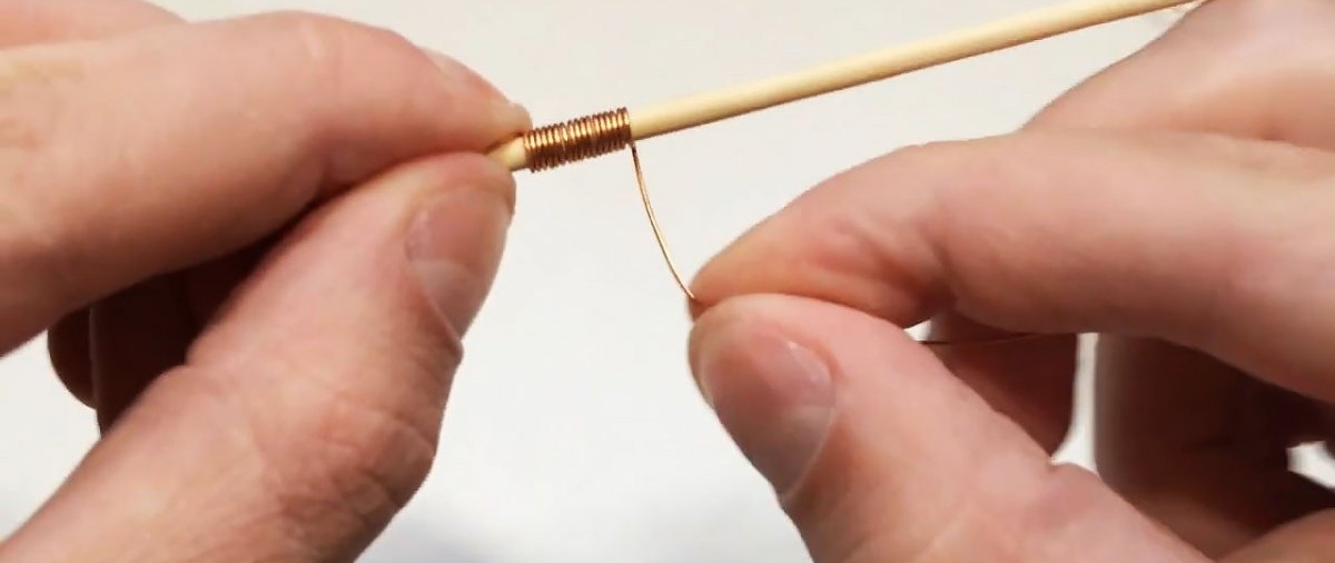
Take out the skewer and stretch the coil a little. The result is an antenna.
Simple hidden wiring detector in 15 minutes

Hidden wiring detector diagram:
Simple hidden wiring detector in 15 minutes

Simple hidden wiring detector in 15 minutes

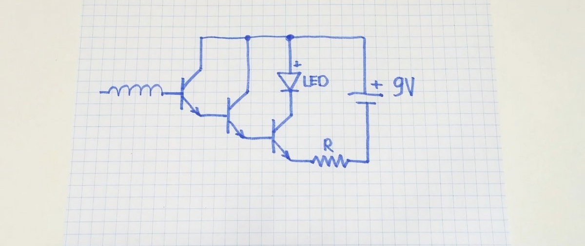
The pinout of the transistor is as follows:
Simple hidden wiring detector in 15 minutes

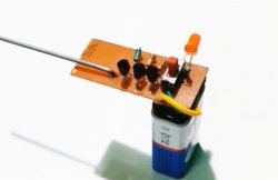
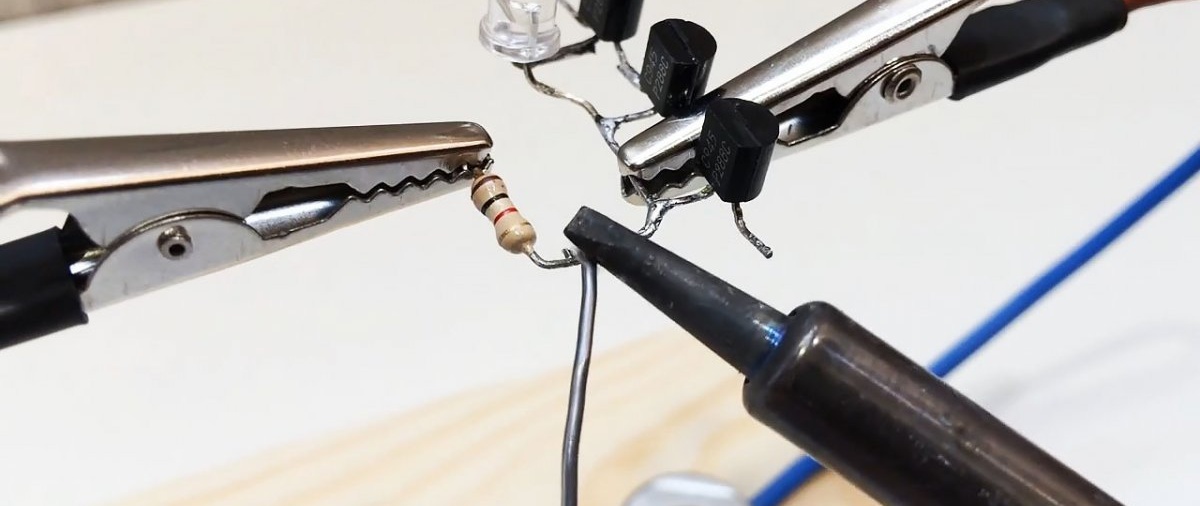
We collect everything according to the diagram. First we solder the transistors to each other.
Simple hidden wiring detector in 15 minutes

The good thing about this 5-part design is that it doesn’t require a board—everything is assembled by surface mounting.
Solder Light-emitting diode.
Simple hidden wiring detector in 15 minutes

Then the resistor.
Simple hidden wiring detector in 15 minutes

We connect the whole thing to the block.
Simple hidden wiring detector in 15 minutes

And finally we solder the antenna.
Simple hidden wiring detector in 15 minutes

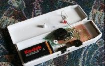
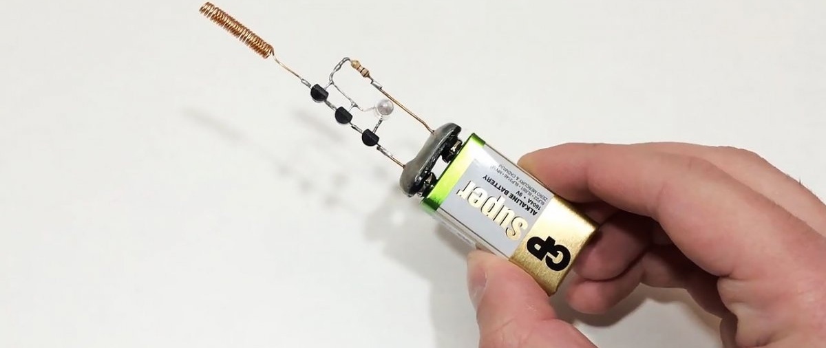
As a result, a ready-made working sample.
Simple hidden wiring detector in 15 minutes

To turn it on, you need to put the block on the battery.
Simple hidden wiring detector in 15 minutes

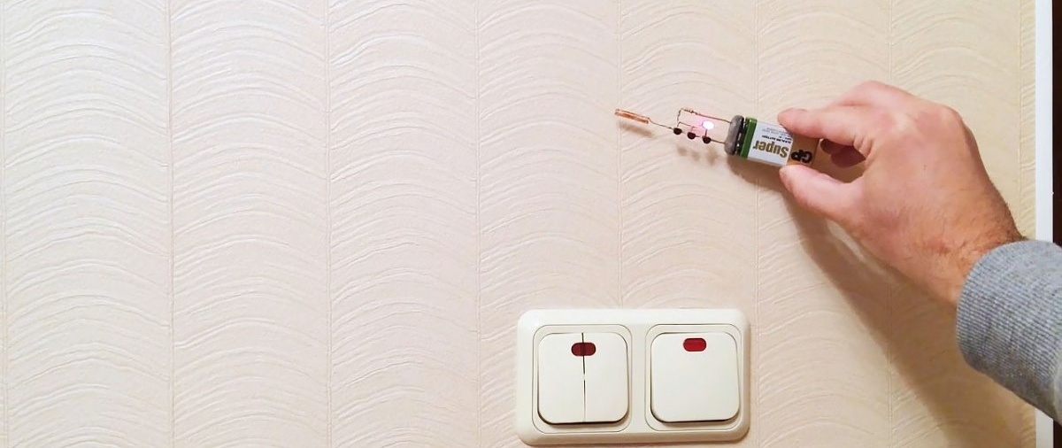
We bring it to the wire:
Simple hidden wiring detector in 15 minutes

Light-emitting diode lights up.
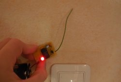
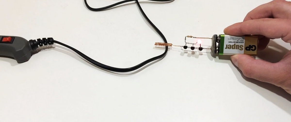
Real world tests:
Simple hidden wiring detector in 15 minutes

When approaching live wiring, Light-emitting diode lights up clearly.
Simple hidden wiring detector in 15 minutes

Such a device does not require any configuration and, if the parts are in good condition, starts working immediately.
Now you can easily identify life-threatening places where you should never drill.

Watch the video


come back
Comment
  • bowtiesmilelaughingblushsmileyrelaxed relaxedsmirk
    heart_eyeskissing_heartkissing_closed_eyesflushedrelievedsatisfiedgrin
    winkstuck_out_tongue_winking_eyestuck_out_tongue_closed_eyesgrinningkissingstuck_out_tonguesleeping
    worriedfrowninganguishedopen_mouthgrimacingconfusedhushed
    expressionlessunamusedsweat_smilesweatdisappointed_relievedwearypassive
    disappointedconfoundedfearfulcold_sweatperseverecrysob
    joyastonishedscreamtired_faceangryragetriumph
    sleepyyummasksunglassesdizzy_faceimpsmiling_imp
    neutral_faceno_mouthinnocent
3+three=
Comments (24)
  1. Drosselmeyer
    #1 Drosselmeyer Guests 30 October 2019 17:23
    5
    Author, it would be better if you didn’t post a photo of your miracle device! There is a resistor on it, which according to the circuit should be connected ONLY to the emitter of the third transistor, is actually connected to the collector of the first and second transistor, and the LED! Light-emitting diode connected between the collectors of the second and third transistor and not connected to the power supply at all.And there’s no need to whine that the soldered device works through it!
    1. Well
      #2 Well Guests October 31, 2019 08:38
      5
      It feels like you “understand” electronics))) It’s because of such masters that everything is like this... Working diagram, don’t chat if you haven’t assembled it!
      1. Drosselmeyer
        #3 Drosselmeyer Guests 31 October 2019 10:41
        3
        Which of the two schemes works? So, which is shown on the electrical circuit diagram or the one that is actually soldered and electrically. scheme NOT figDoesn't it match?
        1. Well
          #4 Well Guests October 31, 2019 11:27
          7
          Yes, both are working! It’s just that in the example made by the author, the resistor is moved to the top between the battery and the collector, pole LED. And the emitter is placed directly on the battery.
    2. Dumbledore
      #5 Dumbledore Guests October 31, 2019 11:22
      5
      In the assembly, the author placed the resistor not in the emitter circuit, as in the diagram, but in the collector circuit. basically nothing has changed
      1. Drosselmeyer
        #6 Drosselmeyer Guests 31 October 2019 12:52
        0
        In mathematics, rearranging the terms does not change the sum, but in electronics, rearranging a resistor from the emitter circuit to the collector circuit can change a lot. In this form, the circuit will work as follows. When the first transistor does not catch the pickup, it is closed, and all other transistors in the circuit are also closed - St. the diode does not light up. At the point (let A) of the connection of the collectors tr. 1 and 2, anode St. diode and resistor, the voltage will be almost equal to the supply voltage. If transistor 1 caught the pickup from the network and opened, transistors 2 and 3 also opened - St. the diode lit up. Voltage drop on St. diode and open tr. 3 will be ~3...4 volts, i.e. This will be the voltage at point A instead of 9 volts. Consequently, the supply voltage of the first two transistors will decrease by approximately 2..3 times.Dear wizard, do we think that nothing has changed? Once again, the diagram I linked to is correct. Email The circuit diagram of this author is correct (with reservations), but the performance of the actually soldered circuit is a BIG question.
        1. Andron
          #7 Andron Guests December 1, 2019 10:47
          9
          Learn to read diagrams. And then you will understand that in this circuit it does not matter where the current limiting resistor will be located!
  2. Drosselmeyer
    #8 Drosselmeyer Guests 30 October 2019 17:28
    0
    1. Dimasik
      #9 Dimasik Guests October 31, 2019 08:39
      1
      And here is the worker, why are you driving?
  3. Rostislav
    #10 Rostislav Guests November 2, 2019 06:48
    4
    In this design, the resistor limits the current completely throughout the entire circuit and no matter where it is located, in the plus or minus circuit. The main thing is that the battery will not splash out its current (150-200 mA) through the junction of the K and E transistors
  4. Guest Nikolay
    #11 Guest Nikolay Guests November 5, 2019 05:46
    0
    This is where all the “electronics” have gathered, I’m a simple person, what can I say: indeed, you can solder this garbage in 15 minutes. But to find components for it, you need to look into more than one garbage dump, and this is a completely different time. It could take weeks, depending on where you live!
    1. Don
      #12 Don Guests November 5, 2019 07:28
      0
      Oh don't talk! Any Chinese board has all the components! You're making up a problem here!
  5. DronSF
    #13 DronSF Guests 5 November 2019 15:34
    1
    I assembled it using MPS2222A transistors (the article says that almost any n-p-n) using video. When connecting the battery Light-emitting diode barely burns. Doesn't respond to wiring. What is the reason?
    1. DronSF
      #14 DronSF Guests 5 November 2019 15:37
      1

      Like this
    2. DronSF
      #15 DronSF Guests 6 November 2019 17:15
      0
      I found 945 transistors and everything worked out
    3. Guest Yuri
      #16 Guest Yuri Guests 11 June 2021 18:20
      0
      you need to set the LEDs to low voltage or mA...miliammeter
  6. Leonov
    #17 Leonov Guests November 10, 2019 12:21
    0
    I assembled the circuit in the same way as the author did in the video. When connecting the crown Light-emitting diode burns constantly. Transistors are fine - checked. What's wrong?
    1. Drosselmeyer
      #18 Drosselmeyer Guests 14 November 2019 15:06
      1
      I provided a link to a competent diagram. Why copy one whose circuit diagram differs from the real one?
      1. Sasha
        #19 Sasha Guests December 30, 2019 20:57
        2
        Drosselmeyer, don't be stupid)) the voltage for the first two transistors will drop by the same amount. It’s just that in one case it’s “on the right”, in another it’s “on the left”, figuratively speaking. But in general, it is needed only to limit the current through the diode and the base-emitter junction of the transistor, as everyone correctly noted. I also soldered it the way the author did, because it was more convenient, and imagine, everything works well. And then I saw that there was such a heated discussion around this resistor.
    2. Guest Vladimir
      #20 Guest Vladimir Guests 16 October 2020 22:08
      1
      Power the circuit from a 3v CR2032 computer battery and you will be happy with this circuit. 100% verified!
  7. Radio amateur
    #21 Radio amateur Guests 13 April 2020 17:16
    4
    It is best to use a field effect transistor as it is more sensitive to the electromagnetic field.
  8. Michael
    #22 Michael Guests 17 May 2021 12:29
    2
    I first assembled it according to the diagram as in the picture, but it doesn’t work. I remade it as in the photo and video and it worked.
  9. Guest Yuri
    #23 Guest Yuri Guests 11 June 2021 15:11
    1
    the circuit can be started from 2 pieces of AAA, you need a 1.7 V diode
  10. Vasya
    #24 Vasya Guests 14 June 2023 16:19
    1
    As soldered, it works. As shown in the diagram - no. At first I also thought that it wouldn’t matter, but for some reason it didn’t.

We decorate clothes with the image of a horse | Do it yourself

Free fertilizer that will increase the yield of tomatoes, peppers and cucumbers

A simple installation for producing gas from gasoline for burning a burner

How to weld a beautiful honeycomb partition from a profile pipe

«Do it yourself - with your own hands» - a site of interesting homemade products made from scrap materials and items at home. Step-by-step master classes with photos and descriptions, technologies, life hacks - everything a real master or just a craftsman needs for needlework. Crafts of any complexity, a large selection of directions and ideas for creativity.

We recommend reading

Washing machine error codes