Do it yourself
Life hacks, master classes, useful tips, recipes.
home » Electronics » Discharge indicator for any battery
Discharge indicator for any battery

This circuit is characterized by a clear switching threshold when the set voltage level is reached. This indicator is universal, has a potentiometer for setting a given value and can work with any battery in the range of 3-16 V.

Will need


  • Two PN2222 transistors, NPN structures.
  • Light-emitting diode 3 V.
  • Variable resistor 10 kOhm.
  • Two 4.7 kOhm resistors.
  • One resistor each 56 kOhm and 460 Ohm.

There are no special requirements for parts; everything can be replaced with similar ones without any problems. In terms of resistors, the deviation from the nominal value can be 10 percent. It's not scary, take those close in meaning.

Manufacturing of a universal discharge indicator


We take the transistors and unbend the terminals.
Discharge indicator for any battery

We solder a 4.7 kOhm resistor to one to its base.
Discharge indicator for any battery

Next, we take the second one and solder it to the same resistor with the collector.
Discharge indicator for any battery

Now we solder another 4.7 kOhm resistor.
Discharge indicator for any battery

Next we solder at 56 kOhm on the left and 460 Ohm on the right.
Discharge indicator for any battery

Solder the potentiometer.
Discharge indicator for any battery

It's getting to work Light-emitting diode.
Discharge indicator for any battery

Complete diagram with all symbols.
Discharge indicator for any battery

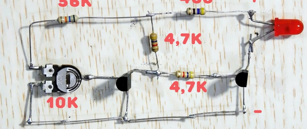
How does the scheme work?


The potentiometer sets the response level, this has already been decided. The transistor on the left contains a threshold element, the transistor on the right contains a key for LED.
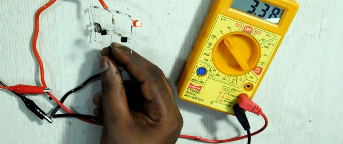
For example, let's set the response level to 3.5 V. If the voltage on the circuit is higher, say 3.6 V, then the first transistor is open and the key is locked. Light-emitting diode in this case it does not light up. The indicator consumes minimal current.
If the voltage drops below the threshold value and is, say, 3.48 V, then the first transistor closes and the key opens. As a result, we see a glow LED, indicating conditionally that the battery is discharged.
Discharge indicator for any battery

The circuit also works perfectly in the 12 V range.
Discharge indicator for any battery

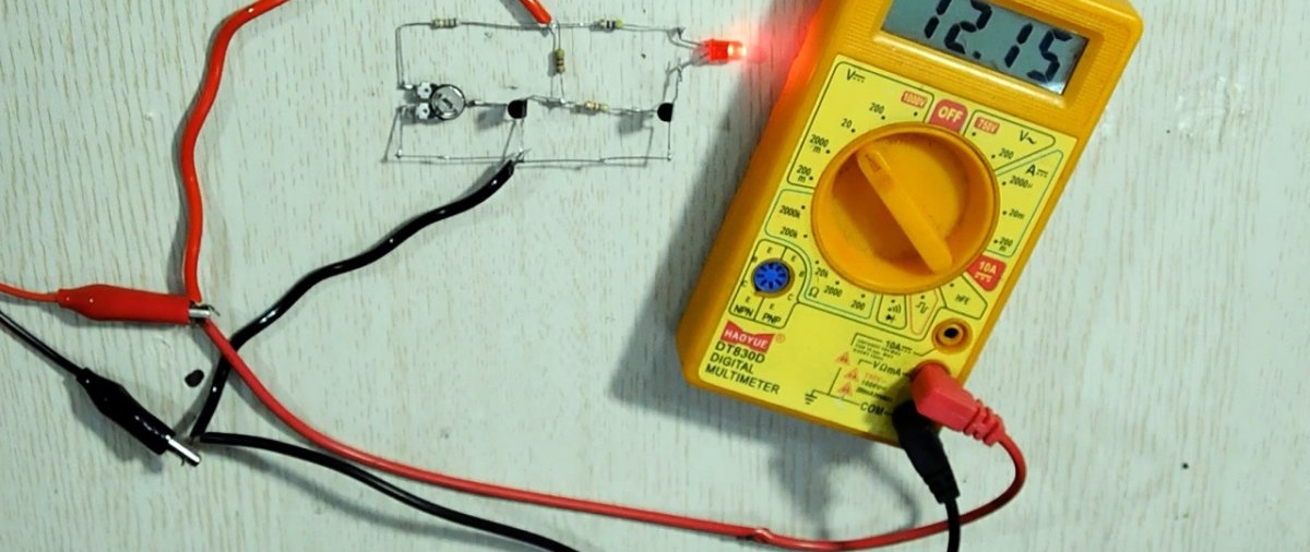
This makes it possible to use the indicator for any batteries or batteries in the range of 3-12 V.

Watch the video


come back
Comment
  • bowtiesmilelaughingblushsmileyrelaxed relaxedsmirk
    heart_eyeskissing_heartkissing_closed_eyesflushedrelievedsatisfiedgrin
    winkstuck_out_tongue_winking_eyestuck_out_tongue_closed_eyesgrinningkissingstuck_out_tonguesleeping
    worriedfrowninganguishedopen_mouthgrimacingconfusedhushed
    expressionlessunamusedsweat_smilesweatdisappointed_relievedwearypassive
    disappointedconfoundedfearfulcold_sweatperseverecrysob
    joyastonishedscreamtired_faceangryragetriumph
    sleepyyummasksunglassesdizzy_faceimpsmiling_imp
    neutral_faceno_mouthinnocent
4 minus one =
Comments (3)
  1. Guest Anatoly
    #1 Guest Anatoly Guests March 3, 2020 11:10
    1
    The video shows that when the voltage increases, it turns on Light-emitting diode! Those. this scheme does not work as the author describes.

    Actually, the original video is signed: “3v-12v Adjustable Battery Full Indicator” - which means “3v-12v Adjustable Battery Full Charge Indicator”, not DISCHARGE

    In the photo "Full diagram with all symbols" - the plus is indicated incorrectly.You need to move it to the connection point of resistors 56k, 460, 4.7k

    To make a good and reliable indicator of battery discharge, I advise you to use a controlled zener diode TL431 and then “sculpt” transistors with LEDs...
  2. Alexander
    #2 Alexander Guests April 24, 2020 10:53
    1
    "The indicator consumes minimal current." If the battery is 12V, then in the duty room it will consume 2.5 mA, I think this is a lot. Industrial batteries are usually equipped with a push-button voltage indicator to prevent discharge.
  3. Guest Alexey
    #3 Guest Alexey Guests 8 December 2021 14:35
    3
    Ehhh, the old Soviet microcircuit KR1170SP, which looks like your three-leg transistor will outshine all your TL431, which certainly has a resistive voltage divider on its control leg with a leakage current of several milliamps, and even more so ancient analog switches. Let's get smaller, comrades))) why is it better - the current consumption will be a few microamps, and the whole circuit is about three elements. For some reason, the discharge indicator will work without any of these English translations

Anyone can make this lathe from a drill.

Vulture | Do it yourself

How to cheaply and environmentally get rid of weeds between paving slabs without unnecessary stress with your own hands

Crafts - Do it yourself, step-by-step master classes | Page 62

«Do it yourself - with your own hands» - a site of interesting homemade products made from scrap materials and items at home. Step-by-step master classes with photos and descriptions, technologies, life hacks - everything a real master or just a craftsman needs for needlework. Crafts of any complexity, a large selection of directions and ideas for creativity.

We recommend reading

Washing machine error codes