Do it yourself
Life hacks, master classes, useful tips, recipes.
home » Electronics » DIY power supply » Simple regulated power supply using three LM317 chips
Hello, today I will tell you how to make an adjustable power supply based on the lm317 chip. The circuit will be able to produce up to 12 volts and 5 amperes.
Simple regulated power supply using three LM317 chips

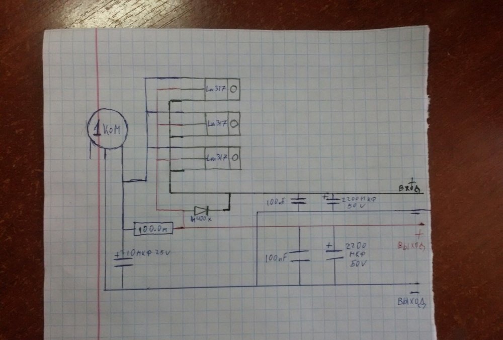
Power supply diagram


Simple regulated power supply using three LM317 chips

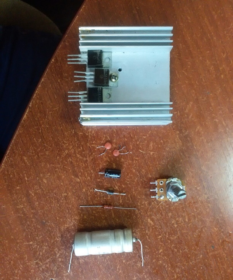
For assembly we need


  • Voltage stabilizer LM317 (3 pcs.)
  • Resistor 100 Ohm.
  • Potentiometer 1 kOhm.
  • Electrolytic capacitor 10 µF.
  • Ceramic capacitor 100 nF (2 pcs.).
  • Electrolytic capacitor 2200 uF.
  • Diode 1N400X (1N4001, 1N4002…).
  • Radiator for microcircuits.
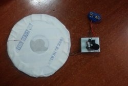
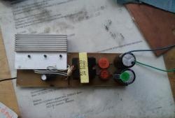
Simple regulated power supply using three LM317 chips

Circuit assembly


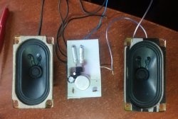
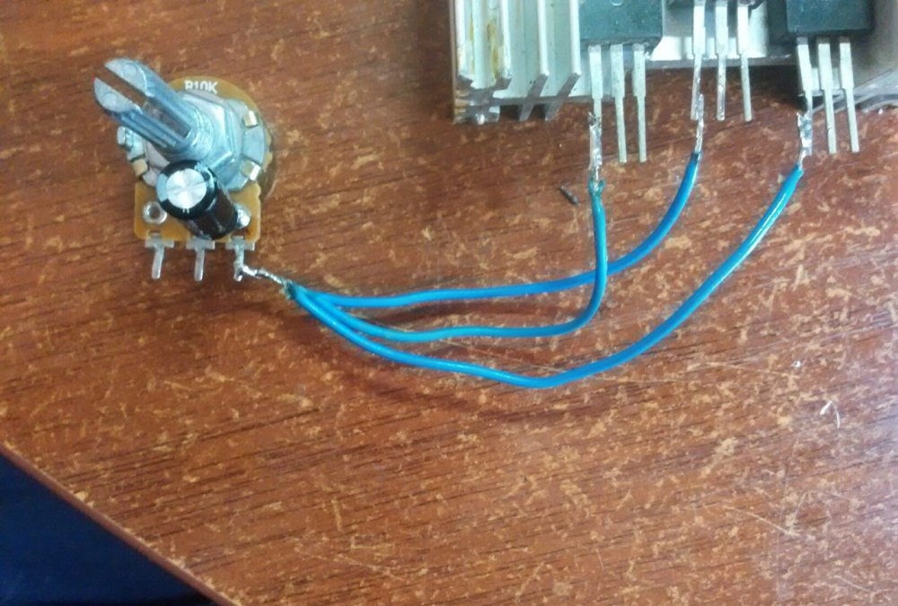
We will assemble the circuit using wall-mounted installation, since there are few parts. First, we attach the microcircuits to the radiator, this will make it easier to assemble. By the way, it is not necessary to use three LMs. They are all connected in parallel, so you can get by with two or one. Now we solder all the leftmost legs to the potentiometer leg. We solder the plus of the capacitor to this leg, and solder the minus to the other output. To prevent the capacitor from interfering, I resoldered it from the bottom of the potentiometer.
Simple regulated power supply using three LM317 chips

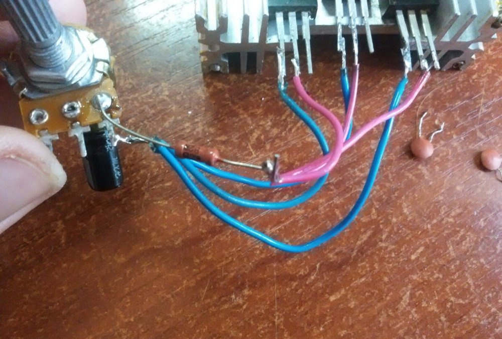
We also solder a 100 Ohm resistor to the potentiometer leg, to which the left legs of the microcircuits were soldered.To the other end of the potentiometer we solder the middle legs of the microcircuits (for me these are purple wires).
Simple regulated power supply using three LM317 chips

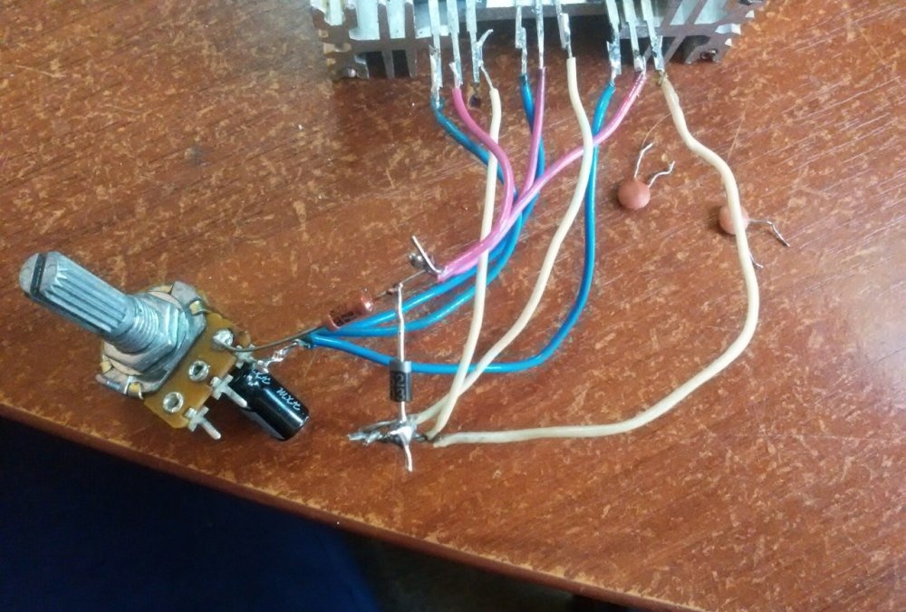
We solder a diode to this resistor leg. To the other leg of the diode we solder all the right legs of the microcircuit (for me these are white wires). Plus we solder one wire, this will be the plus of the input.
Simple regulated power supply using three LM317 chips

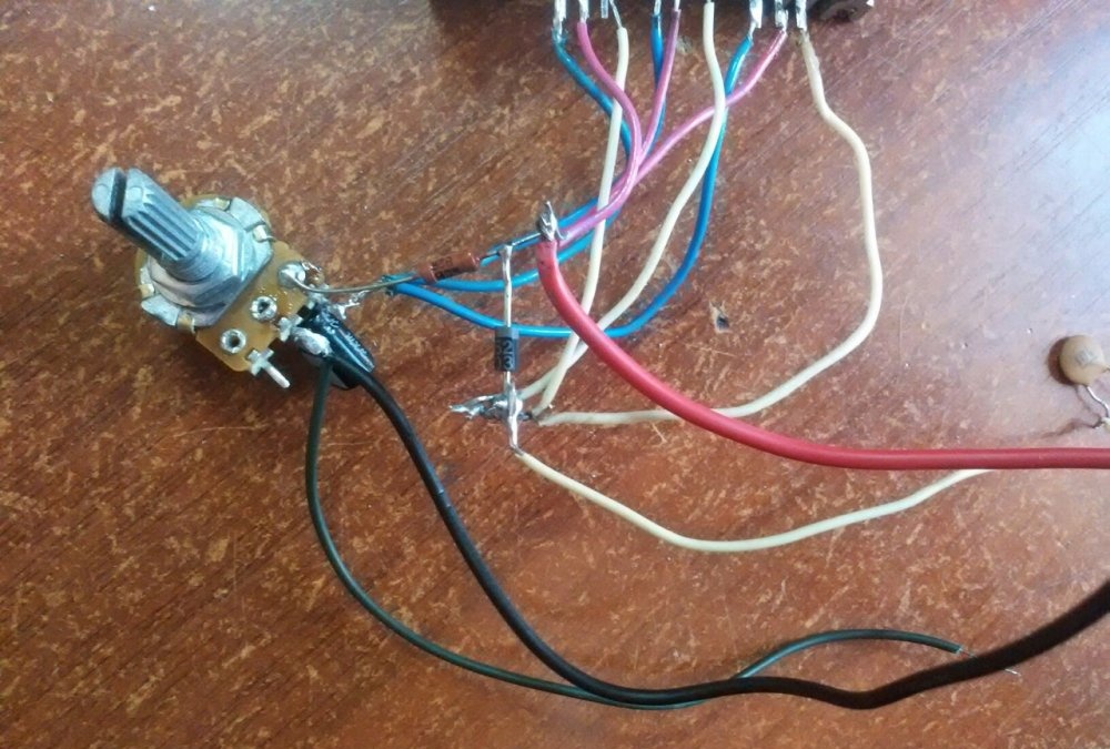
We solder two wires to the second output of the potentiometer (mine are black). This will be minus entry and exit. We also solder the wire (mine is red) to the resistor where the diode was previously soldered. This will be a plus for the exit.
Simple regulated power supply using three LM317 chips

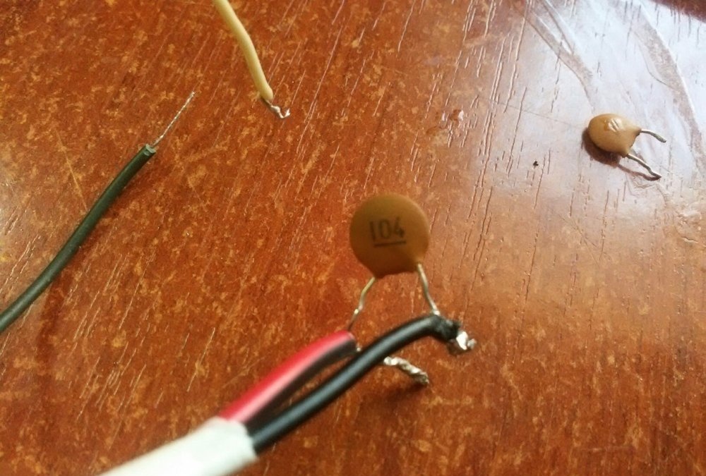
Now all that remains is to solder to the plus and minus of the input, plus and minus of the output via a 100 nF capacitor (100 nF = 0.1 µF, marking 104).
Simple regulated power supply using three LM317 chips

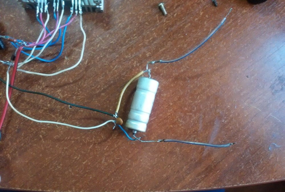
Next we solder a 2200 µF capacitor to the input, the positive leg is soldered to the input positive.
Simple regulated power supply using three LM317 chips

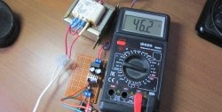
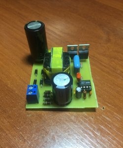
At this point, the production of the circuit is ready.
Simple regulated power supply using three LM317 chips

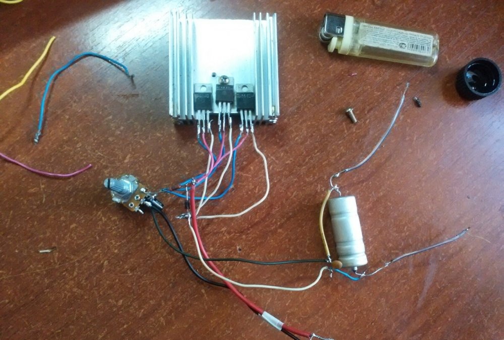
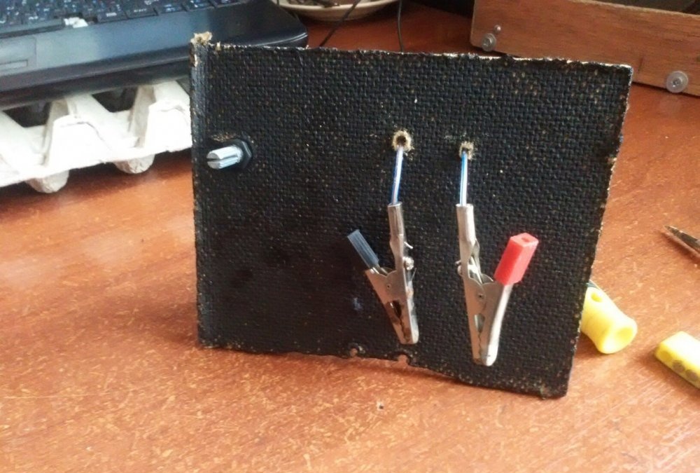
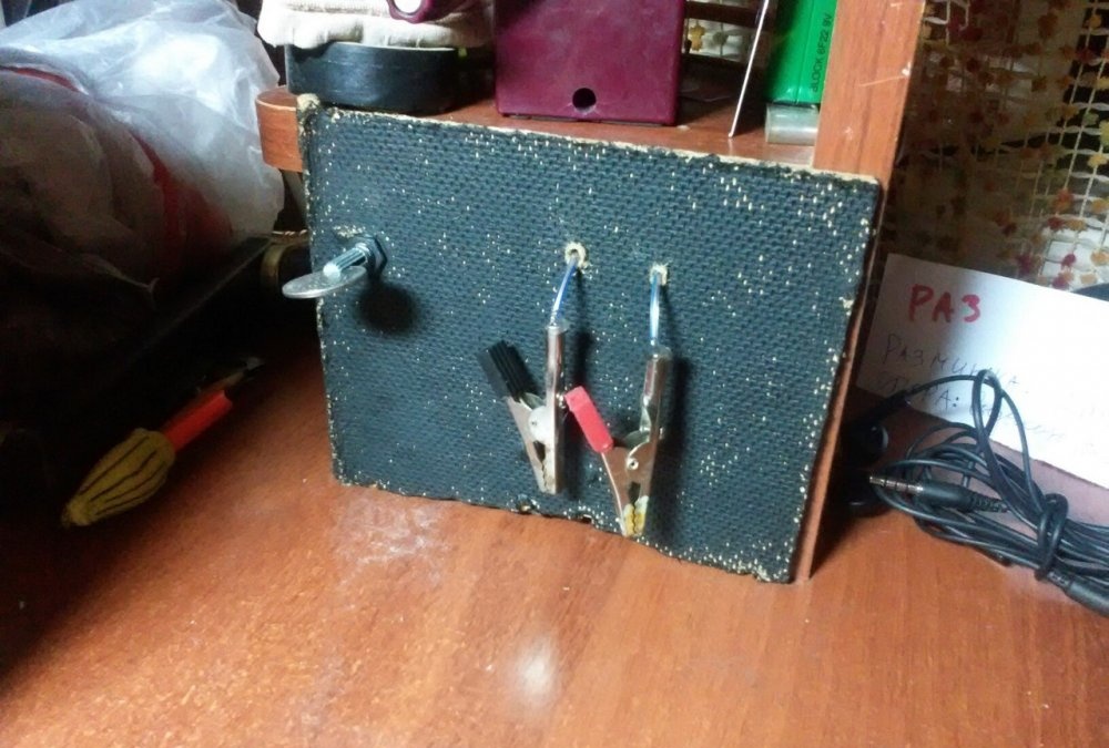
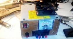
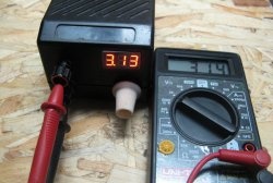
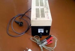
Since the circuit produces 4.5 Amps and up to 12 Volts, the input voltage should be at least the same. We will now use a potentiometer to regulate the output voltage. For convenience, I advise you to install at least a voltmeter. I won't make a full body; all I did was attach the heatsink to a piece of fiberboard and screw on the potentiometer. I also brought out the output wires and screwed the crocodiles to them. It's quite convenient. Next, I attached it all to the table.
Simple regulated power supply using three LM317 chips

Simple regulated power supply using three LM317 chips
come back
Comment
  • bowtiesmilelaughingblushsmileyrelaxed relaxedsmirk
    heart_eyeskissing_heartkissing_closed_eyesflushedrelievedsatisfiedgrin
    winkstuck_out_tongue_winking_eyestuck_out_tongue_closed_eyesgrinningkissingstuck_out_tonguesleeping
    worriedfrowninganguishedopen_mouthgrimacingconfusedhushed
    expressionlessunamusedsweat_smilesweatdisappointed_relievedwearypassive
    disappointedconfoundedfearfulcold_sweatperseverecrysob
    joyastonishedscreamtired_faceangryragetriumph
    sleepyyummasksunglassesdizzy_faceimpsmiling_imp
    neutral_faceno_mouthinnocent
5+two=
Comments (8)
  1. Sergey K
    #1 Sergey K Visitors March 2, 2018 10:55
    4
    I wouldn't put too much hope in such a power supply. A parallel switching circuit is possible, but it is necessary to leave at least a 50 percent power reserve - microcircuits, even of the same series, even modern ones, all have a variation in parameters. And if the power exceeds the power of an individual microcircuit, some of them will work at the limit, and maybe overload and eventually fail. It's good if it's just a stabilizer! Or maybe the powered circuit will bark...
    If you really need a current of 5A, then maybe it’s better to use LM338? Or unsolder LM1083 (7.5A) or LM1084 (5A) from old motherboards
  2. Guest Andrey
    #2 Guest Andrey Guests March 2, 2018 12:40
    6
    That electronics specialists no longer know how to draw electrical circuits.
  3. Guest Vlad
    #3 Guest Vlad Guests 2 March 2018 13:30
    3
    I circle one circuit with a transistor and the amperage turns out to be more, well, in general, it’s not for everyone
  4. Guest Sergey
    #4 Guest Sergey Guests 4 March 2018 23:01
    14
    Just quiet horror. The author would do it for himself on the sly, but would be ashamed to publish this. Before publishing, I would have looked at how variable resistors are designated in the diagram. This design will most likely burn out at a current of 4.5 A, since no measures have been taken to equalize the current through the stabilizers. And if it doesn’t burn out, consider yourself lucky - the built-in protection worked. In addition, for the output voltage to be 12 V, the input must be at least 1.5 V higher.
  5. Guest Nikolay
    #5 Guest Nikolay Guests March 29, 2018 02:59
    4
    Post THIS on the internet? Ashamed! A current is required that exceeds the capabilities of the stabilizer chip - add a powerful transistor and a 6-10 ohm resistor. A transistor and a microstabilizer on radiators is easier and more reliable.
  6. Guest Oleg
    #6 Guest Oleg Guests 19 February 2019 12:17
    0
    The author, don’t listen to anyone, it’s a shame for someone there, it’s not a shame. Well done and posted it. I support yours starting.
  7. Guest Maxim
    #7 Guest Maxim Guests January 30, 2021 09:03
    0
    Author, thank you
  8. Alec
    #8 Alec Guests March 9, 2021 04:52
    0
    Horrible!
    the power will triple, but the leveling circuit for the lmcock mode is complicated - see the datasheet on the chip!
    Well, the diagram d.b. drawn, and not a la Picasso!

Vintage New Year gift wrapping | Do it yourself

A simple and cheap cyclonic dust collector for a vacuum cleaner made of two buckets

Gerbera clip | Do it yourself

Charger for Li-Ion (Li-Po) batteries from an “electronic cigarette”

«Do it yourself - with your own hands» - a site of interesting homemade products made from scrap materials and items at home. Step-by-step master classes with photos and descriptions, technologies, life hacks - everything a real master or just a craftsman needs for needlework. Crafts of any complexity, a large selection of directions and ideas for creativity.

We recommend reading

Washing machine error codes