High-voltage technology is a special direction in electronics, which has its own unique spirit, aesthetics and features. Thousands of enthusiasts around the world are building various designs, ranging from simple multipliers to huge Van de Graaff generators and Tesla coils - as a rule, all these devices do not have any practical application, their value lies precisely in the creation of colorful high-voltage discharges.

The most affordable element capable of generating high voltage can confidently be called a line transformer - this element is present in any CRT TV; at the moment, the price of such transformers is becoming very low, given that CRT TVs are gradually becoming a thing of the past. Two types of such transformers can be distinguished - TDKS, with a built-in multiplier, and TVS - a “bare” transformer, to which the multiplier can be connected separately.In both cases, in order to make such a transformer produce high voltage, a special circuit is needed that will “pump” its primary winding with a high-frequency voltage; this frequency can vary between 1-100 kHz. There are quite a large number of similar circuits on the Internet, often simple single-ended circuits using only one powerful transistor, which closes and opens the circuit of the primary winding of a line transformer with the required frequency - such circuits, although simple, have a fairly low efficiency (the transistor gets very hot) and low power, thus, do not allow the full potential of the transformer to be revealed and the maximum possible power to be removed from it - and the length, strength and brightness of the discharges directly depend on the power.
Scheme
The circuit presented in this article is a classic half-bridge converter based on the IR2153 microcircuit; it can develop quite a lot of power in the load - up to 500 watts when using the appropriate transistors at the output, and with minor modifications even a few kilowatts. At the same time, the circuit itself looks very simple to assemble, does not contain any expensive elements and is highly repeatable.

The load of the circuit is inductance L1 - in our case it is the primary winding of the line transformer. But also based on this circuit, it is possible to assemble various other devices that require high-frequency voltage and large amplitude, for example, an induction heater. For clarity, the picture below shows the signal shape at the output of the circuit without a connected load - almost ideal rectangular pulses.

A little about the details and operation of the converter
The IR2153 microcircuit acts as a push-pull rectangular pulse generator - it is push-pull because there are two outputs (pins 5 and 7) and the microcircuit simultaneously controls two field-effect transistors, the upper and lower arms. This microcircuit is not in short supply; some network power supplies and other switching devices are built on its basis; the price for it in radio components stores usually does not exceed 100 rubles. This microcircuit is convenient in that it already contains a zener diode inside, which allows the microcircuit to be powered from the same voltage as the load - this voltage for effective operation of the half-bridge should be 100-300 volts, thus, an additional low-voltage source is not required to power the logical part of the circuit . The resistor that limits the current through the zener diode of the microcircuit is R1 - its value is marked with an asterisk in the diagram. The resistance of this resistor will depend on the supply voltage of the entire circuit - the higher the supply voltage, the higher the resistance value will be; you can calculate the exact value for any supply voltage by using a calculator to calculate the zener diode resistor. The rating indicated in the diagram is suitable for a supply voltage of 250 volts. It should also be taken into account that some power will be dissipated on this resistor, so it is necessary to use either one 1-3 watt resistor, or several low-power ones in parallel, as done on a printed circuit board. Capacitor C2 serves to filter the supply voltage of the microcircuit; its value can be from 100 to 220 μF, the voltage is at least 25 volts.Capacitor C1 is a high-voltage power supply; you should not skimp on its capacity, because the power at the load will depend on it - if the capacity is too small, power drawdowns may occur and the power will decrease. The optimal value would be 470-680 uF; note that this capacitor must be designed for a high supply voltage + some margin.
The chain of elements R2-C3 sets the frequency, so it is important to use a high-quality high-frequency capacitor here; a regular film capacitor will do. The larger the capacitance of the capacitor, the lower the operating frequency of the circuit; at the indicated ratings it is approximately equal to 80 kHz. You can assemble a circuit with a fixed frequency, but the best results can be obtained if you can adjust the frequency, so instead of a constant resistor, I recommend installing a 20 kOhm trimmer; the range of frequency adjustments can also be selected by the capacitance of the capacitor. Capacitor C4 - it is advisable to use a non-polar tantalum capacitor with a capacity of 20-30 µF, but a regular electrolytic one will do. Resistors R3, R4 serve to limit the current in the gates of transistors, suitable for 10-30 Ohms.
Particular attention should be paid to the choice of power transistors, because they are the ones who will switch the load and both the efficiency of the circuit and its reliability will depend on them. The most inexpensive, but not the most powerful option is the IRF630 - they are suitable for operating at voltages of no more than 150 volts with not too much power, I use them.You can use almost any powerful field-effect transistors here; when choosing, you should take into account their maximum operating voltage, current and open-channel resistance. Suitable options would also be IRF740, IRF840, IRFP450, IRFP460, the last two are more expensive, but will allow you to operate at higher powers, up to 500 watts. Capacitors C5 and C6 form a voltage divider, which is necessary for the operation of a half-bridge converter; film capacitors with a capacity of 1-2 μF can be used here; their operating voltage must also be designed for the supply voltage + some reserve. VD1 is a diode; you need to use here not ordinary diodes, but ultra-fast ones, for example UF4007 and similar ones.
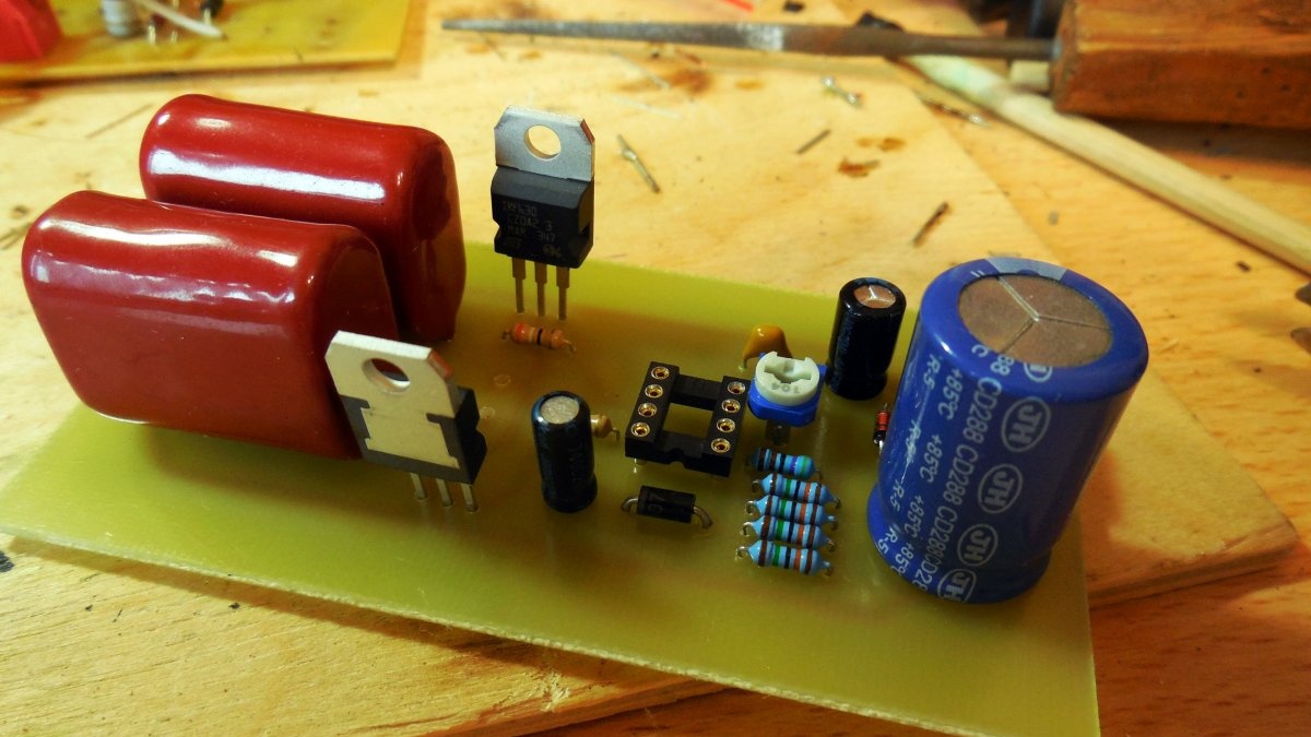
Converter assembly
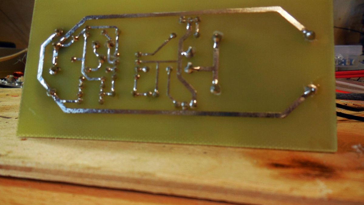
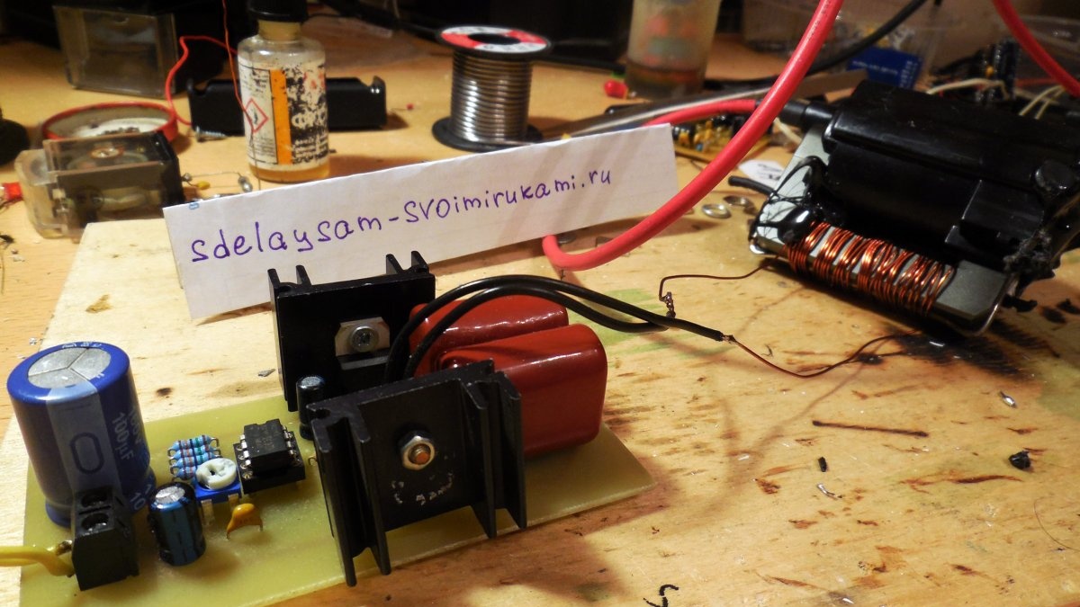
The entire circuit is assembled on a printed circuit board, which is attached to the article. Please note that the circuit is “capricious” in terms of wiring; this version of the board is tested, no artifacts were detected in the work on it. The board is made using the standard LUT method, photographs of the process of making the board and sealing the parts are below.


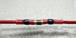
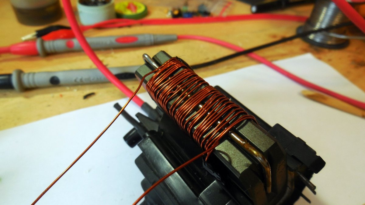
A few words about the primary winding - it must be wound on the ferrite core of the transformer yourself, since standard primary windings are not designed for high power. Winding does not take much time, only 30-40 turns of enameled copper wire are enough, its cross-section should not be too small, otherwise losses will occur. The resulting winding must be connected to the board with wires, and their length should not be too long.
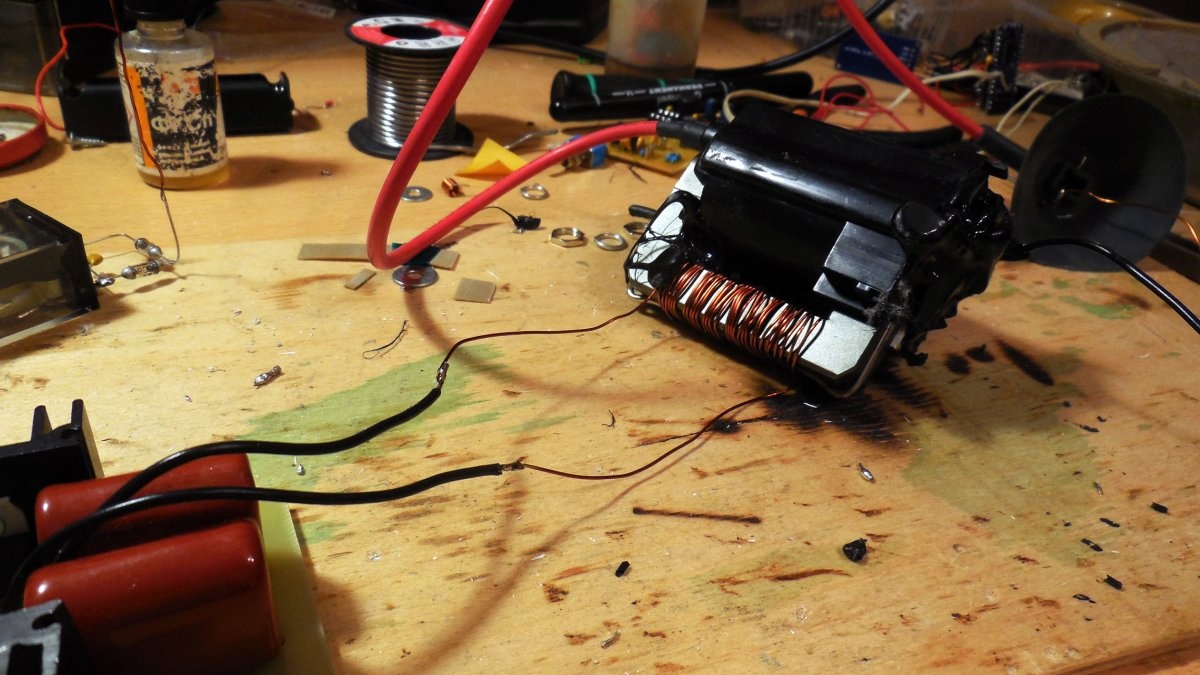
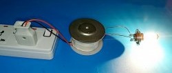
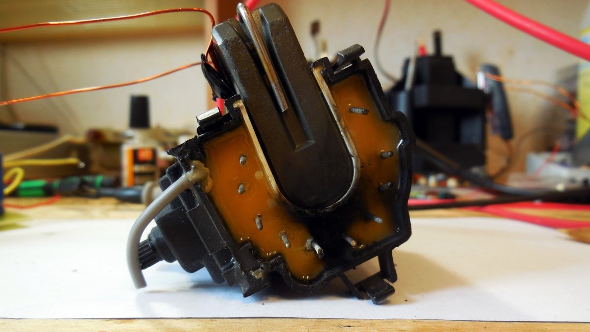
As you might guess, high voltage is removed from the “hot” terminal of the transformer, which can usually be identified by thick insulation.The negative contact on the TDKS is located in the lower part of the case along with all the other terminals; it is easy to find - just look at which contact the arc will light when the “hot” terminal is approached. Please note that the lower part of the TDKS in the photograph has blackening - they were formed when the TDKS was working with this half-bridge circuit, since the transformer is used almost to the limit of its capabilities, sometimes breakdowns occur between its different terminals. To avoid them, you should fill all the terminals with a dielectric compound, and bring out only the required negative wire with a separate wire.
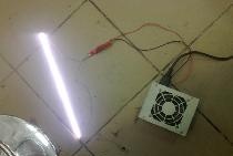
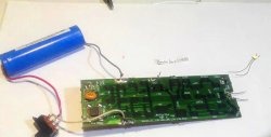
The entire structure must be powered from a source with appropriate power; it is convenient if the supply voltage can be adjusted. In my case, the power source is the old transformer of their TS-160 tube TV; for rectification, a diode bridge with capacitors on a small board is separately connected, it can be seen in the photo.

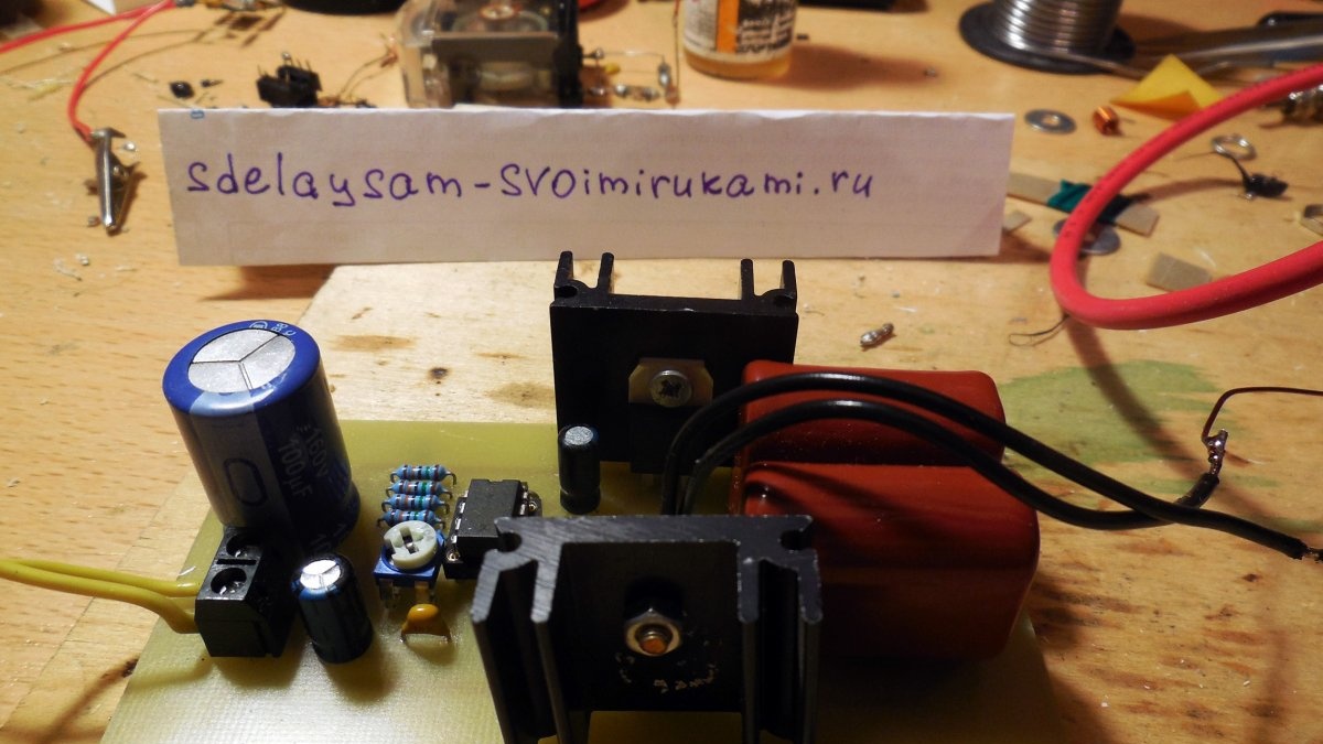
Even such “low-power” transistors as the IRF630 in this circuit do not get very hot; after several minutes of continuous operation they remain only warm on small radiators. Although the heat dissipation is small, especially when using, for example, IRFP450-560, small radiators like in the photo for reliability will not be superfluous. General view of the design:
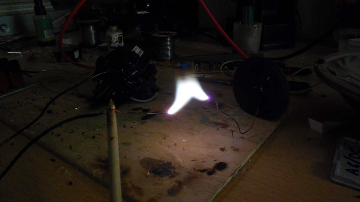
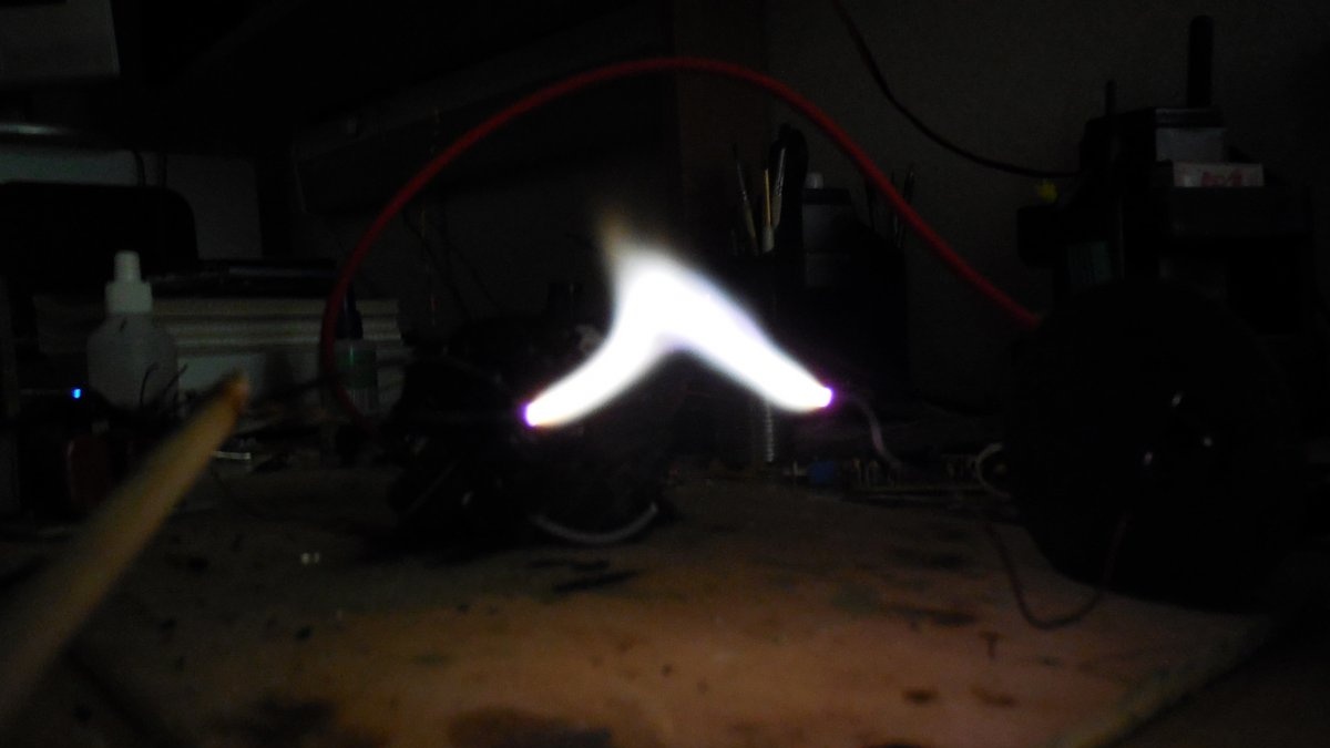
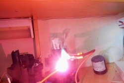
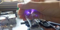
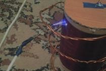
Concluding photographs - which depict high-voltage arcs, as well as video. The breakdown voltage of air is approximately 3 centimeters. As can be seen in the video, if the high-voltage electrodes are placed at a certain distance from each other, the arc does not burn, and the transformer operates idle, while violet discharges are coronaed from its “hot” terminal, as well as from the housing itself - when they appear, it is advisable to isolate all possible places of breakdowns by dielectric compound.Please note that TDKS not only has high voltage, but also sufficient power to cause electrical injury if you touch the high-voltage terminals with your hands. Touch is not even necessary for an arc to occur, given the fairly large breakdown distance. It should also be remembered that after turning off the circuit, the high voltage at the TDKS output still remains, since there is a capacitor inside, so after turning off the high-voltage terminals should be connected to each other to discharge this capacitor. Happy building!