Do it yourself
Life hacks, master classes, useful tips, recipes.
home » Electronics » We control the load with one button. How to make a powerful latched switch using a MOSFET
This key, built on powerful field-effect transistors, is designed to control the load by pressing a clock button: one press - turn on, press again - turn off.
We control the load with one button How to make a powerful switch using a MOSFET

This key is good because it does not interfere with the circuit. Thanks to the use of powerful mosfets, the resistance of the switch in the open state is thousandths of an ohm. At these values, even when driving a powerful load, no transistor heatsinks are required. When using bipolar transistors, such parameters cannot be achieved.

Parts you will need


  • Transistors IRFZ44N - 2 pieces -
  • Transistors IRF4905P - 2 pieces -
  • Resistors: 10 kOhm, 47 kOhm, 510 kOhm.
  • Capacitor 0.1 µF.
  • Tact button.

Scheme


We control the load with one button How to make a powerful fixed switch on a MOSFET

The first transistor switches the load, the second serves to hold the desired position.

Making an electronic switch using MOSFET


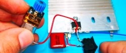
We tin and unbend the output of the IRFZ44N transistor.
We control the load with one button How to make a powerful switch using a MOSFET

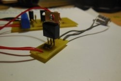
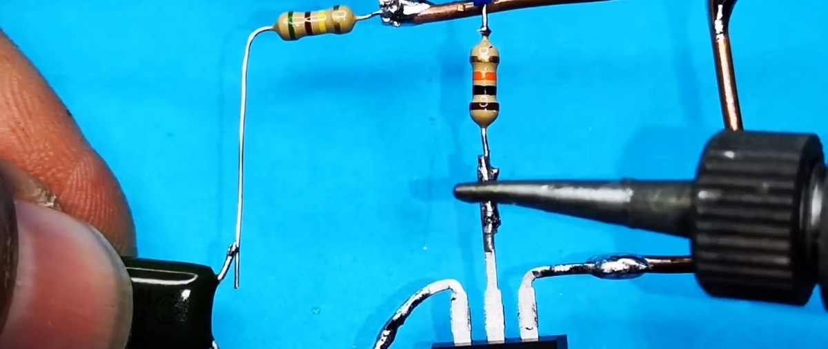
Solder a 47 kOhm resistor between the source and gate. We solder a 10 kOhm resistor to the gate.
We control the load with one button How to make a powerful fixed switch on a MOSFET

We solder the IRF4905P transistor to the 10 kOhm resistor as a source. We solder the gate to the drain of the IRFZ44N.
We control the load with one button How to make a powerful fixed switch on a MOSFET

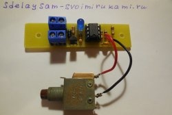
We solder the power buses from thick wire.
We control the load with one button How to make a powerful fixed switch on a MOSFET

Solder the resistor and capacitor according to the diagram.
We control the load with one button How to make a powerful fixed switch on a MOSFET

At the end there is a tact button without fixation.
We control the load with one button How to make a powerful fixed switch on a MOSFET

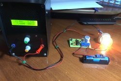
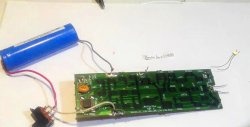
The scheme is ready. We use an incandescent lamp as a load. The device will be powered from 12 V.
We control the load with one button How to make a powerful fixed switch on a MOSFET

We press the button, the lamp lights up.
We control the load with one button How to make a powerful fixed switch on a MOSFET

Press again - it goes out.
Maximum voltage: 60 V, maximum current: 50 A - according to the datasheet for the control transistor.

Watch the video


come back
Comment
  • bowtiesmilelaughingblushsmileyrelaxed relaxedsmirk
    heart_eyeskissing_heartkissing_closed_eyesflushedrelievedsatisfiedgrin
    winkstuck_out_tongue_winking_eyestuck_out_tongue_closed_eyesgrinningkissingstuck_out_tonguesleeping
    worriedfrowninganguishedopen_mouthgrimacingconfusedhushed
    expressionlessunamusedsweat_smilesweatdisappointed_relievedwearypassive
    disappointedconfoundedfearfulcold_sweatperseverecrysob
    joyastonishedscreamtired_faceangryragetriumph
    sleepyyummasksunglassesdizzy_faceimpsmiling_imp
    neutral_faceno_mouthinnocent
5+two=
Comments (7)
  1. Guest Denis
    #1 Guest Denis Guests December 12, 2020 00:00
    2
    It is not at all necessary to use a powerful IRFZ44 mosfet as T2. A low-power SMD, for example 2N7002, will do; I used BST82.
  2. Guest Alexander
    #2 Guest Alexander Guests 4 May 2021 15:07
    0
    I assembled a circuit with the same denominations, but it didn’t work. After I replaced the capacitor from 0.1 μF with a 470 μF electrolyte and a resistor from 510k to 100k, it began to work, but unstable and with a long delay, because... The electrolyte needs time to charge.I can’t understand what’s going on here? I watched the video 10 times and couldn’t find any errors in the printed circuit board. Can anyone tell me what the catch is?
    1. Well
      #3 Well Guests 4 May 2021 17:01
      0
      Your transistors probably have a low transmission ratio
      1. Guest Alexander
        #4 Guest Alexander Guests 5 May 2021 01:32
        0
        I used the same transistors as in the article!
  3. Guest Alex
    #5 Guest Alex Guests 16 September 2021 19:08
    1
    The 47k resistor is soldered not to Z44, but to something else. The circuit works at 7-8 volts. 10v and higher stops turning off.
  4. Guest Yuri
    #6 Guest Yuri Guests 12 December 2021 14:50
    0
    Why did he write there that we solder the IRF4905P transistor to the 10 kOhm resistor as the source, and in the figure we soldered it to the drain... was he confused or misleading? The average is 4905-drain according to the circuit
  5. Guest Alexander
    #7 Guest Alexander Guests 11 February 2022 15:45
    0
    In the photos of the assembly the mosfets are mixed up.
    If you assemble according to the diagram, then it’s normal.

Napkin with embroidered roses | Do it yourself

Adding a relay block to the car: DRL, recorder, pneumatic signal

5 tricks for laying tiles

How to make a simple folding fishing boat

«Do it yourself - with your own hands» - a site of interesting homemade products made from scrap materials and items at home. Step-by-step master classes with photos and descriptions, technologies, life hacks - everything a real master or just a craftsman needs for needlework. Crafts of any complexity, a large selection of directions and ideas for creativity.

We recommend reading

Washing machine error codes