Do it yourself
Life hacks, master classes, useful tips, recipes.
home » Electronics » DIY electronics » Turn on and off the load with one button

Many household electrical appliances, be it stereo systems, televisions, various lamps, are turned on and off by pressing the same button. Pressed once - the device turned on, pressed again - turned off. In amateur radio practice there is often a need to implement the same principle. Such buttons are often used when building homemade amplifiers in elegant cases; a device with this principle of switching on and off looks much more advanced, reminiscent of a factory device.

Device diagram

The diagram for turning the load on and off with one button is presented below. It is as simple as boots, does not contain scarce components and starts up immediately. So, the diagram:

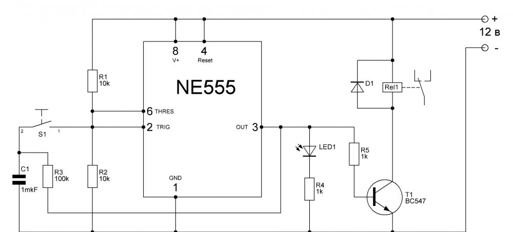
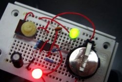
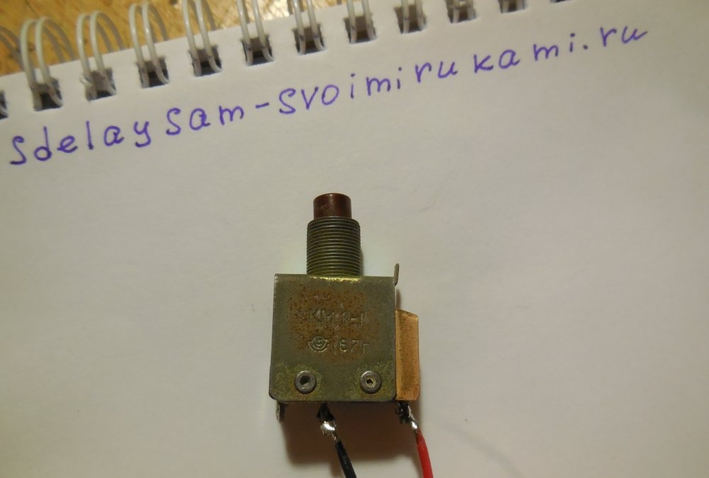
Its key link is the popular NE555 timer chip. It is this that registers the key press and sets the output to either logical 1 or 0. Button S1 is any button for closing without fixing, because There is practically no current flowing through it, there are practically no requirements for the button. I took the first one I came across, a Soviet one from the 60s.

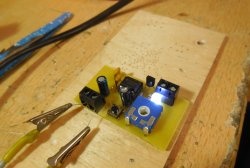
Capacitor C1 and resistor R3 suppress the bounce of the button contacts; C1 is best used non-polar ceramic or film. Light-emitting diode LED1 indicates the load status – Light-emitting diode On, the load is on, off - off. Transistor T1 switches the relay winding; here you can use any low-power transistor of the NPN structure, for example, BC547, KT3102, KT315, BC184, 2N4123. A diode placed parallel to the relay winding serves to suppress self-induction pulses arising in the winding. You can use any low-power diode, for example, KD521, 1N4148. If the load consumes little current, you can connect it directly to the circuit instead of the relay coil. In this case, it is worth installing a more powerful transistor, for example, KT817, and the diode can be eliminated.

Materials

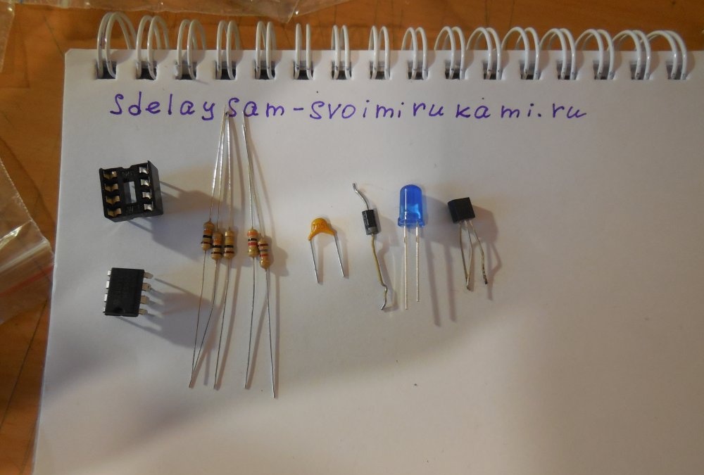
To assemble the circuit you will need:

  • Chip NE555 – 1 pc.
  • Transistor BC547 – 1 pc.
  • Capacitor 1 uF - 1 pc.
  • Resistor 10 kOhm – 2 pcs.
  • Resistor 100 kOhm – 1 pc.
  • Resistor 1 kOhm – 2 pcs.
  • Button without fixation – 1 pc.
  • Diode KD521 – 1 pc.
  • Light-emitting diode at 3 in. - 1 PC.
  • Relay – 1 pc.

In addition, you need a soldering iron, flux, solder and the ability to assemble electronic circuits. Electronic components cost almost a penny and are sold in any radio parts store.

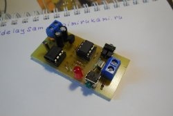
Assembling the device

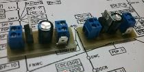
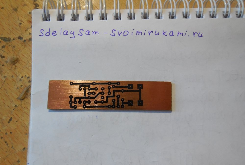
First of all, you need to make a printed circuit board. It is performed using the LUT method, the file is attached to the article. There is no need to mirror before printing. The LUT method has been described several times on the Internet, and it is not that difficult to learn. A few photos of the process:

Download the board:

pechatnaya-plata.zip [5.04 Kb] (downloads: 2847)

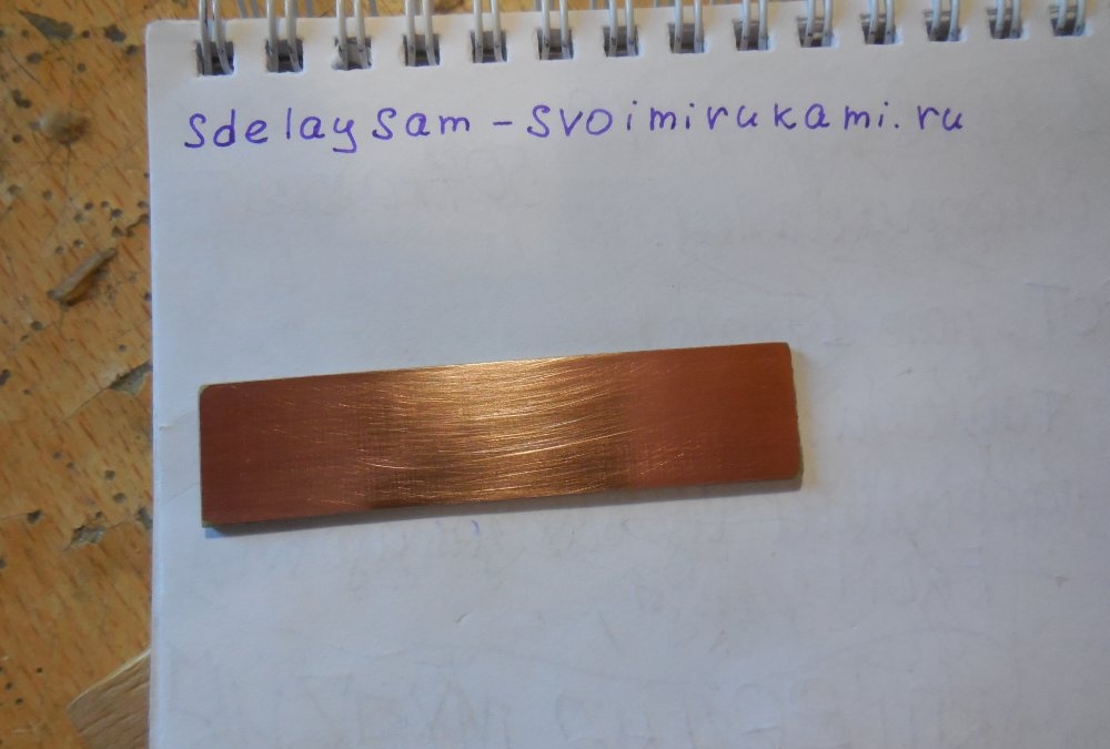
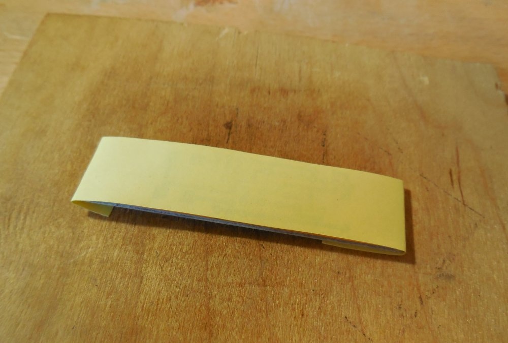
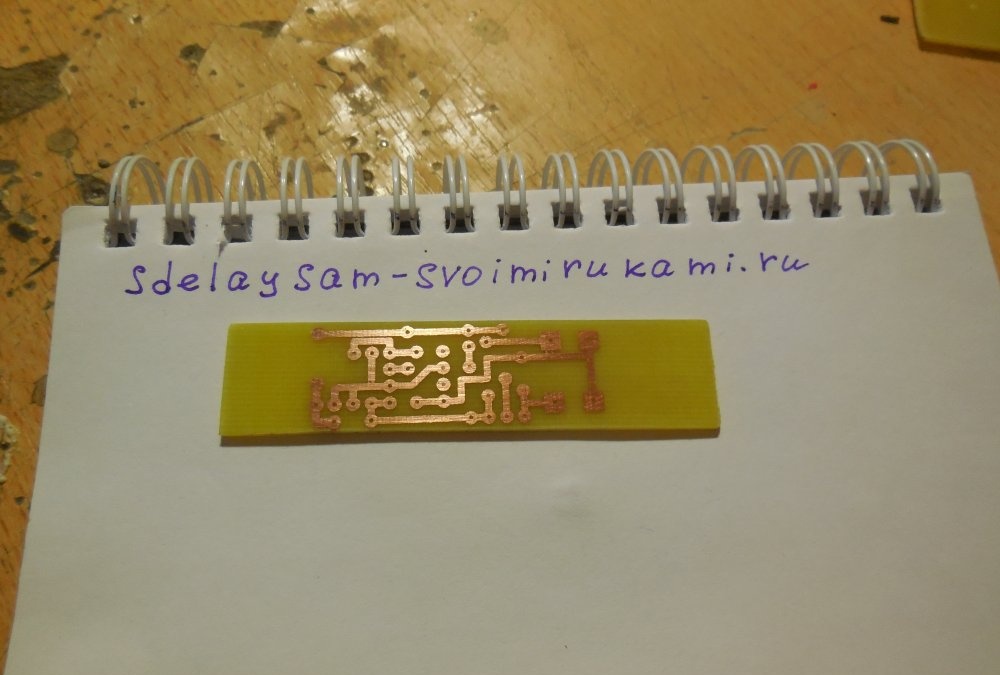
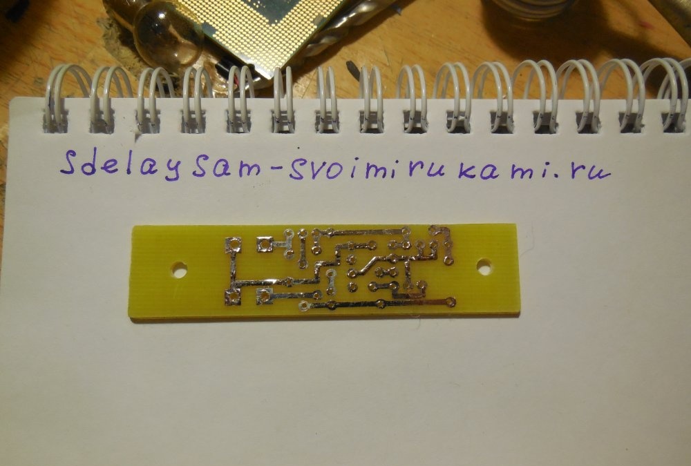
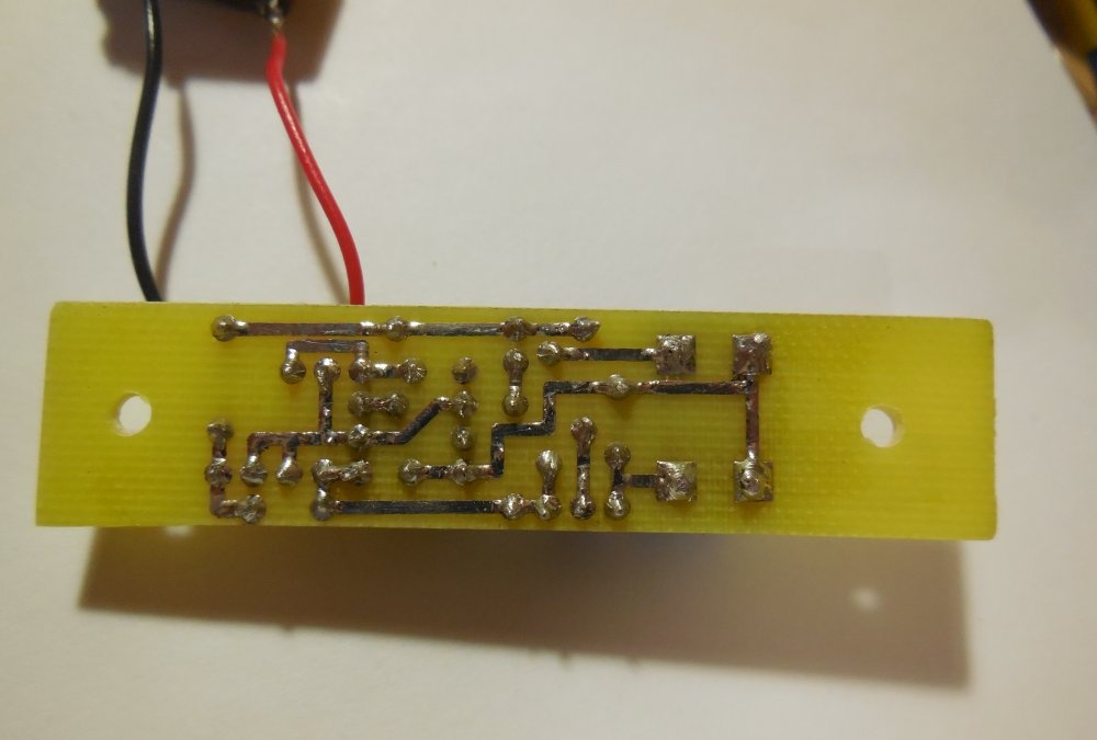
If you don’t have a printer at hand, you can draw a printed circuit board with a marker or varnish, because it is quite small. After drilling the holes, the board must be tinned to prevent oxidation of the copper traces.

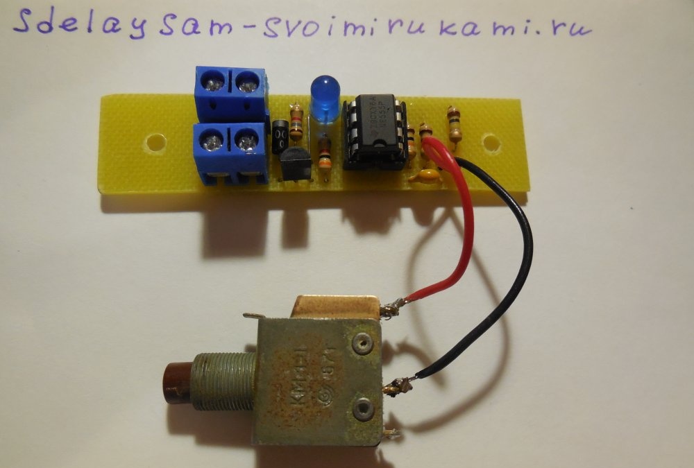
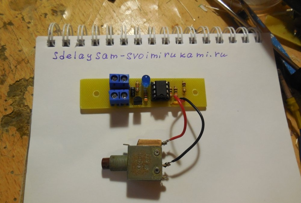
After making the board, you can start soldering parts into it. First, small components are soldered - resistors, diodes. After that, capacitors, microcircuits and everything else. The wires can be either soldered directly into the board or connected to the board using terminal blocks. I brought out the power contacts and OUT contacts for connecting the relay through terminal blocks, and soldered the button directly into the board using a pair of wires.

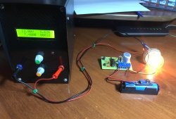
Thus, this board can be built into any device, be it an amplifier, a homemade lamp, or anything else that requires turning it on and off with one button without locking. There are many other similar circuits on the network, built on Soviet microcircuits and transistors, but this particular circuit using the NE555 microcircuit has proven itself to be the simplest and at the same time reliable.

Watch the video

The principle of operation is clearly shown in the video.

come back
Comment
  • bowtiesmilelaughingblushsmileyrelaxed relaxedsmirk
    heart_eyeskissing_heartkissing_closed_eyesflushedrelievedsatisfiedgrin
    winkstuck_out_tongue_winking_eyestuck_out_tongue_closed_eyesgrinningkissingstuck_out_tonguesleeping
    worriedfrowninganguishedopen_mouthgrimacingconfusedhushed
    expressionlessunamusedsweat_smilesweatdisappointed_relievedwearypassive
    disappointedconfoundedfearfulcold_sweatperseverecrysob
    joyastonishedscreamtired_faceangryragetriumph
    sleepyyummasksunglassesdizzy_faceimpsmiling_imp
    neutral_faceno_mouthinnocent
5+two=
Comments (25)
  1. Guest Fedor
    #1 Guest Fedor Guests 8 April 2018 18:48
    2
    The diode is placed in parallel with the relay winding for other purposes. To protect against breakdown of the key transistor. Since in the inductance (relay winding) the voltage leads the current.
    1. Guest Mikhail
      #2 Guest Mikhail Guests 8 April 2018 20:26
      6
      Both the author and Fedor say the same thing about the diode, but in different words, because it is the self-induction emf that breaks through the transistor, which is many times greater than the supply voltage.
  2. Hippopotamus
    #3 Hippopotamus Guests 8 April 2018 22:05
    10
    what do you teach beginners? There are three jumpers on a board with two parts.
  3. Alexander
    #4 Alexander Guests 9 April 2018 19:48
    0
    All this in the presence of a standby power supply of 12 Volts, which is not advisable. The duty station should be 5 Volts, any smartphone charger will handle it
  4. Yuriyod1979
    #5 Yuriyod1979 Guests April 22, 2018 09:41
    5
    I don't need 5 volts! 12 is just right! Just right for the car!
  5. totik
    #6 totik Guests 6 July 2018 13:28
    4
    Thank you, I was just looking for a design like this!
  6. Denis SunTi
    #7 Denis SunTi Guests August 28, 2018 01:43
    2
    But I didn’t understand something, where is the relay in the finished device? It’s there on the diagram, it’s in the necessary parts, but it’s not on the printed circuit board or in the finished device. In fact, it turns out that the button only turns on/off Light-emitting diode, and power is supplied to the load regardless of whether the button is connected or not.
    1. iglitsa
      #8 iglitsa Guests 31 January 2019 22:56
      3
      and it was really funny. I was also looking for a relay =)
      The finished board has 2 pair terminals - input and output. so you need to connect a relay to the output
  7. Guest Sergey
    #9 Guest Sergey Guests January 2, 2019 10:42
    3
    Thanks for the circuit, but it has a drawback: it is better to pull pin 5 of the microcircuit to ground through a capacitor, this way you can get rid of false positives.
    I used it on a pump control circuit, I was tired of the constant operation, sometimes when the power is turned on, sometimes due to interference in the network.
    Simulation in multisim showed that the circuit is with open pin 5. When power is applied abruptly, it remains in the off state. If a filter in the form of a capacitor is installed at the power input, the supply voltage increases more slowly and the circuit acquires an on state.
    If pin 5 is connected through a capacitor, then the circuit turns on only when the button is pressed.
    1. Guest Alexey
      #10 Guest Alexey Guests January 18, 2019 06:53
      4
      What capacitor capacity is better to install?
  8. Guest Sergey
    #11 Guest Sergey Guests January 27, 2019 08:44
    1
    What capacitance should I put on the 5th leg of the NE555 chip?
  9. Vitaly Nezhelsky
    #12 Vitaly Nezhelsky Guests 6 February 2019 14:21
    9
    This device does not work. everything is assembled according to the scheme from serviceable parts. There are no installation errors. no snot. When you touch your toes 6 and 7, there is a rattling sound when turning on and the switch is not turned on confidently. If it wants to turn on, but if it doesn’t want to, it won’t turn on. I don’t know what’s wrong. in the comments it was said for a resistor on the fifth leg to the ground .. what value should I set approximately? Is 1k enough?
  10. Vitaly Nezhelsky
    #13 Vitaly Nezhelsky Guests 6 February 2019 14:22
    2
    I'm sorry... not a resistor.. what capacity should I install???

How to insulate a floor with a gas block with your own hands

DIY quilling for beginners | Page 2

Why is the bayonet knife not sharp?

Toys-bells for the Christmas tree | Do it yourself

«Do it yourself - with your own hands» - a site of interesting homemade products made from scrap materials and items at home. Step-by-step master classes with photos and descriptions, technologies, life hacks - everything a real master or just a craftsman needs for needlework. Crafts of any complexity, a large selection of directions and ideas for creativity.

We recommend reading

Washing machine error codes