The switch is designed primarily to control 12-volt automotive safety lighting bulbs, which are installed in cellars and other places with high dampness, where this is required for electrical safety reasons. Can be used for switching other low-voltage loads with power up to 100 W. Contains a minimum number of non-scarce and inexpensive radio components that are available in regular and online stores.

Circuit features of the switch
The switch is connected in series with the load and receives power from the same source. Made in the form of a transistor trigger, it is triggered when the button is pressed once. Suppression of button contact bounce to protect against false triggering is ensured by the introduction of an integrating RC circuit. The device diagram is shown in the figure.

- powerful field effect transistors IRFZ-44N (T1) and IRF-4905 (T2) - http://alii.pub/5ct567
- resistors with a power of 0.25 W and nominal values of 10 kOhm, 47 kOhm and 470 kOhm - http://alii.pub/5h6ouv
- bipolar capacitor with a capacity of 100 nF - http://alii.pub/5n14g8
- button with normally open contacts - http://alii.pub/5nnu8o

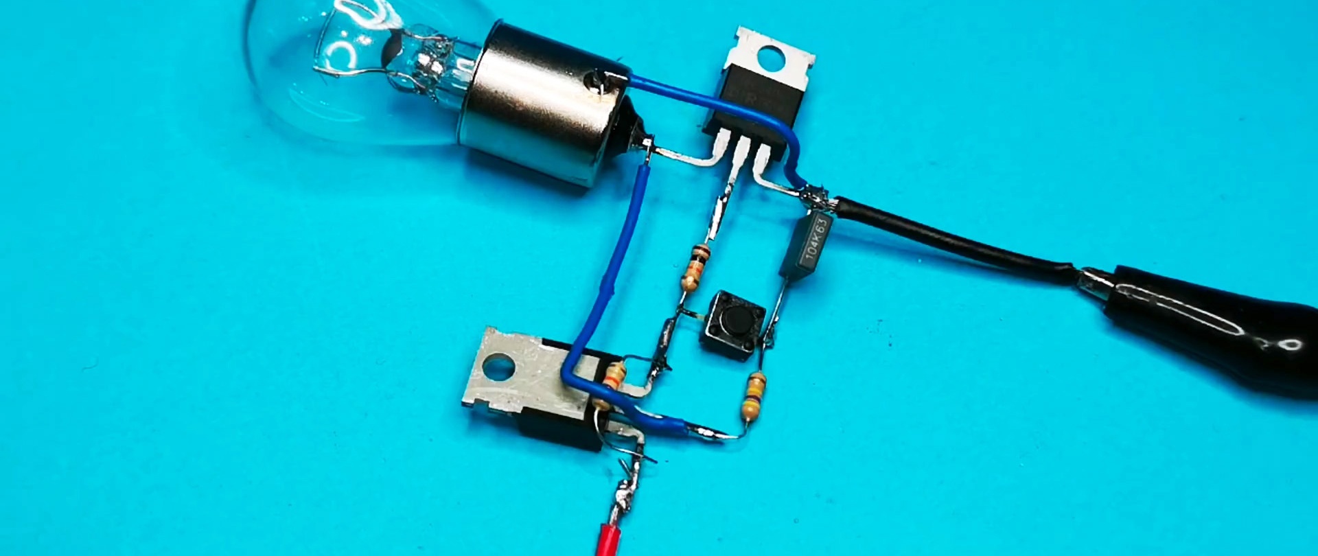
The transistors are made in the same type of housing and have a plate radiator, which is directly connected to the drain. The pinout and bending of the leads recommended during assembly is shown in the figure.
Making the switch
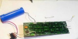
The switch is compact and can easily be assembled on a getinax or textolite printed circuit board, even with one-sided foil. You can make the board yourself without etching. In this case, areas for mounting parts are formed with a surgical lancet, awl or other suitable sharp object, which is used to cut through the metallization layer.
It is recommended to place individual elements on the board as shown in the circuit diagram. The order in which the elements are installed on the board does not matter; after soldering, excess leads are removed with side cutters.


- before soldering, the metallization areas should be cleaned with fine sandpaper until shiny;
- The radiators of the transistors are at drain potential and should not touch each other or other conductive circuits.
When assembled correctly, the switch is ready for operation immediately after connecting to the power source and does not require preliminary configuration. If resistors and a capacitor of the required value are not available, they can be replaced with similar ones; a deviation of resistance and capacitance of up to 15% in both directions is permissible. The device remains operational in the source voltage range of at least 10 – 14 V.