Do it yourself
Life hacks, master classes, useful tips, recipes.
home » Electronics » DIY amplifier » Sound amplifier on TDA2030A chip

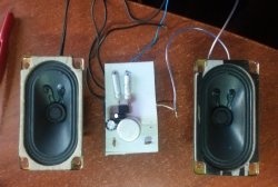
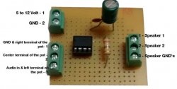
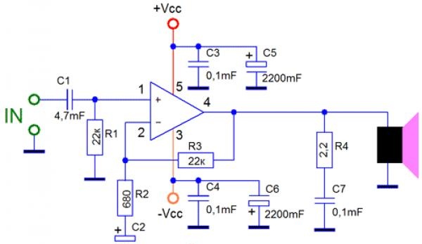
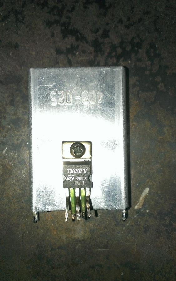
I found an unnecessary circuit board from a TV. The TDA203A microcircuit caught my eye. I know that TDA brand microcircuits are low frequency amplifiers, there is a lot of information about them on the Internet. I decided to build my own simple amplifier according to the scheme:
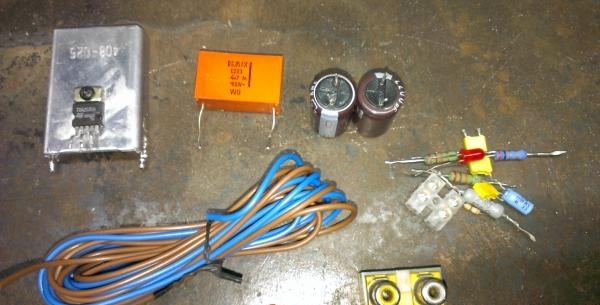
Sound amplifier on TDA2030A chip

Needed for assembly

  • Chip TDA2030A.
  • Capacitors 0.1 uF - 3 pieces.
  • Capacitors 2200 uF 25 V - 2 pieces.
  • Resistor 2.2 Ohm.
  • Resistors 22 kOhm - 2 pieces.
  • Resistor 680ohm.
  • Capacitor 22 uF 25 V.
  • 4.7 µF film capacitor.
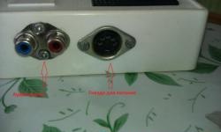
  • Housing, switch, wires, radiator, connectors for tulips.
Sound amplifier on TDA2030A chip

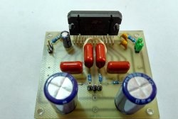
Assembling a simple amplifier on TDA2030

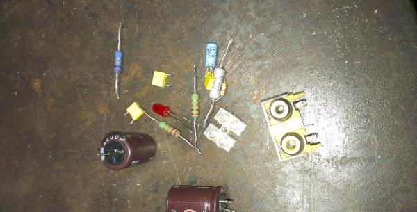
My goal was to create an amplifier without spending a lot of money on it. I found all the parts except the housing in various old boards that were not needed naturally.

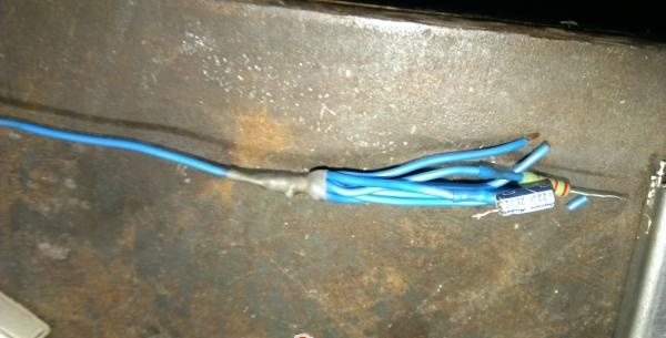
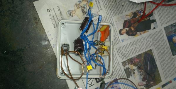
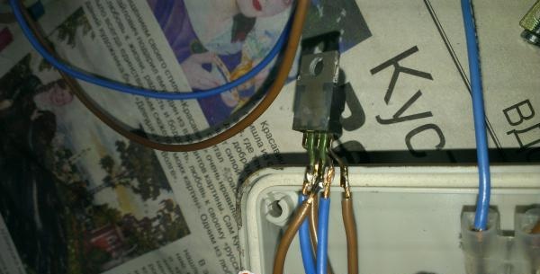
You can assemble an amplifier on a TDA2030 using different methods and solutions; in this case, I will use wall-mounted installation. Since many pins are connected to ground, I recommend making a branching wire.

Sound amplifier on TDA2030A chip

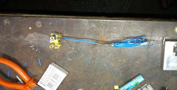
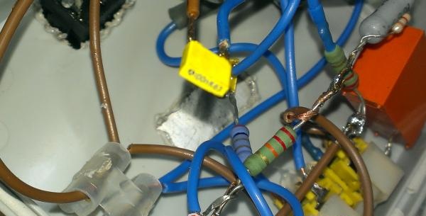
Next we proceed to soldering the connections.

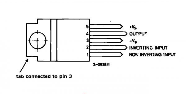
The microcircuit pins are counted from left to right, with the markings and pins directed towards you.

Sound amplifier on TDA2030A chip

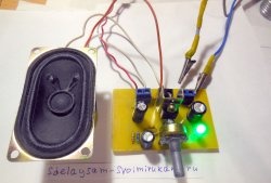
After you have assembled the circuit, we check it. Let's connect the speaker and test the amplifier at low volume.

Sound amplifier on TDA2030A chip

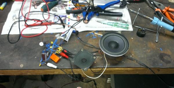
If everything works, we proceed to the next stage.

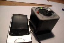
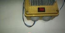
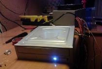
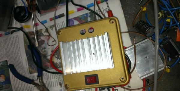
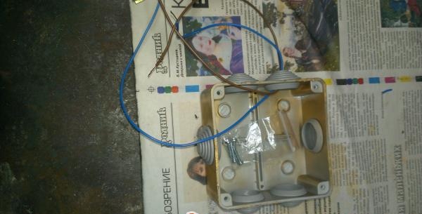
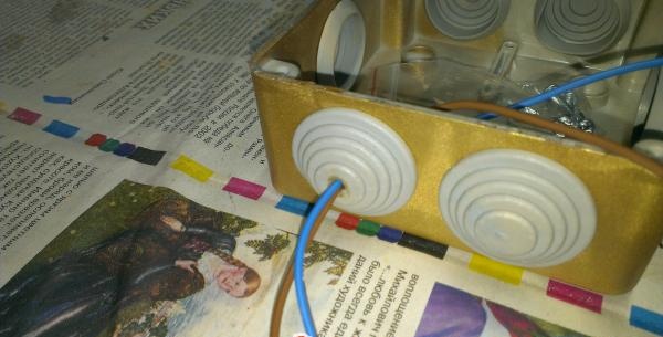
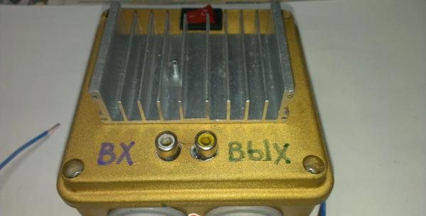
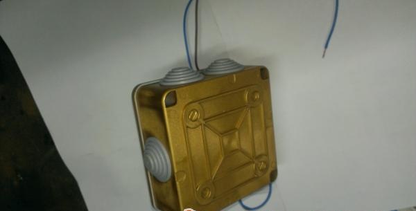
I had a ready-made body. It is better to take the radiator outside for better cooling of its surface. Otherwise, overheating may occur in the case.

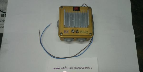
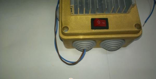
Attach the radiator, connectors, bring out the power wires, and install the power switch.

Sound amplifier on TDA2030A chip
The amplifier has the following characteristics:
  • Supply voltage - from ±4.5 to ±25 V.
  • Output power - 18 W.
  • Nominal frequency range - 20-80,000 Hz.

Almost all such microcircuits get very hot and therefore will not work for a long time without a heatsink.

Sound amplifier on TDA2030A chip
Final look:
Sound amplifier on TDA2030A chip

This is a truly incredibly simple circuit that even novice radio amateurs can assemble. With all this, it has decent characteristics for its minimal size.

Collect your amplifier and you will be happy, friends.

come back
Comment
  • bowtiesmilelaughingblushsmileyrelaxed relaxedsmirk
    heart_eyeskissing_heartkissing_closed_eyesflushedrelievedsatisfiedgrin
    winkstuck_out_tongue_winking_eyestuck_out_tongue_closed_eyesgrinningkissingstuck_out_tonguesleeping
    worriedfrowninganguishedopen_mouthgrimacingconfusedhushed
    expressionlessunamusedsweat_smilesweatdisappointed_relievedwearypassive
    disappointedconfoundedfearfulcold_sweatperseverecrysob
    joyastonishedscreamtired_faceangryragetriumph
    sleepyyummasksunglassesdizzy_faceimpsmiling_imp
    neutral_faceno_mouthinnocent
5+two=
Comments (64)
  1. Andrey
    #1 Andrey Guests October 8, 2013 21:38
    4
    Hello, a very good article, but I can’t figure out the circuit, but I really want an amplifier, please draw what to solder where
    1. Edward
      #2 Edward Guests February 15, 2018 00:43
      2
      Well, what is unclear here? There is a diagram, legs 1-5.The strapping is soldered to these legs as shown in the diagram and voila
      Look, the schemes are the same everywhere. The legs are still the same.
  2. having fallen
    #3 having fallen Guests 13 January 2014 16:58
    1
    Quote: Andrey
    Hello, a very good article, but I can’t figure out the circuit, but I really want an amplifier, please draw what to solder where
  3. Dmitriy
    #4 Dmitriy Guests January 18, 2014 11:47
    2
    Guys, what is there to figure out? Solder according to the diagram, the ratings are all there, the pins are marked as grounding in the common bundle, and on the minus, the radiator is larger for ms, and the thermal paste is thicker)) I’m going to solder it myself today.
  4. Dmitriy
    #5 Dmitriy Guests 23 January 2014 13:36
    0
    I soldered this unit the other day, but! It doesn’t sing, with 4 ohm it’s silent, with 8 ohm the diffuser jumps in the dynamics, and that’s it, the question is where is the mistake? I checked the circuit several times, the power supply was 7.5V, and 12.0V, at 7.5V there was no effect at all (((
  5. Andriano
    #6 Andriano Guests 1 March 2014 19:24
    3
    Hello) I assembled this amp practically from garbage, put it in a burnt-out sub, and was shocked, the bass is even, it works for about 3-4 hours, thanks for the article, I’ll take a closer look at that stuff
  6. Kolyan
    #7 Kolyan Guests 30 March 2014 20:09
    2
    Hello)) I assembled this circuit, and I didn’t have the C5 element; I replaced it with two 1000 uF and two 100 uF parallel connections. And turning it on, after 3-5 seconds the transistor exploded, the voltage was 10.5 volts.
    And from this the question: Did he explode because of this replacement? If not, then why? I'm just not good at it.
  7. Kostyan
    #8 Kostyan Guests 4 April 2014 23:26
    5
    No, not because of this. Most likely I mixed up something in the connection of the microcircuit. I spent ten years assembling the circuit, everything worked, but this circuit requires high-quality assembly, namely:
    1. Good radiator.
    2. Supply power reserve.
    3. Power wires must have a minimum cross-section of 2mm2.Otherwise, the amplifier will go into self-excitation at a very high frequency and die.
    If everything works, but the sound is not clear with distortion (metallic), increase the power and power filtering.
    And you will be happy.

    The power and clear sound is amazing.
  8. Vova
    #9 Vova Guests 23 April 2014 03:23
    2
    Guys, is it possible to replace the film capacitor with something?
  9. Nikitos
    #10 Nikitos Guests June 29, 2014 03:32
    2
    Why are tulips “input and output”? Output of what? Jack + 2 tulips cable?
  10. Nikita
    #11 Nikita Guests July 7, 2014 03:03
    1
    Thanks for the diagram, very cool amp!!! Deep clear sound!!!

Second life for a laptop with a broken screen

The simplest transformerless power supply for an LED matrix

Lie detector. | Do it yourself

Making the switch backlight | Do it yourself

«Do it yourself - with your own hands» - a site of interesting homemade products made from scrap materials and items at home. Step-by-step master classes with photos and descriptions, technologies, life hacks - everything a real master or just a craftsman needs for needlework. Crafts of any complexity, a large selection of directions and ideas for creativity.

We recommend reading

Washing machine error codes