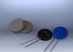
I decided to use a small ionization chamber with a current amplifier built on a compound transistor as a sensor.
But when I connected the base of the compound transistor directly to the sensor wire, there was virtually no collector current. I expected to see some leakage current due to the “floating base” and a gain of tens of thousands. I don't know if all composite npn transistors are as good as these MPSW45A, but the leakage current was surprisingly low and the gain looked very high, perhaps 30,000, with a base current of several tens of picoamps. (I checked the gain using a 100 MΩ test resistor connected to a power supply with regulated output voltage.)
Suddenly I saw an opportunity to use these common components to make a really sensitive sensor. I have added another transistor as shown below
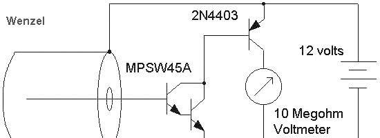
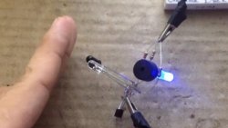
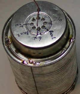
Who needs bias resistors?! I used a tin can about 10 cm in diameter with a hole in the bottom for the antenna wire and aluminum foil to cover the open part.I quickly realized that a resistor connected to the 2N4403 base (10k) is a good idea to prevent short circuit damage. The performance of this circuit was excellent and easily detected the Thorium glow grid of a Coleman lamp! So why not add another compound transistor? It seemed funny, but here's what I came up with:
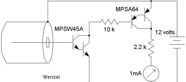
I used a 9V supply voltage, but would recommend using a slightly higher voltage to obtain sufficient potential in the ionization chamber. Resistors were added to protect against accidental short circuits, which could quickly destroy a transistor or ammeter. During normal operation, they have little effect on the operation of the circuit.
This circuit worked really well and after the 5-10 minutes it took to stabilize, it could detect the glow grid at a distance of about ten centimeters. But the circuit turned out to be sensitive to temperature changes and the ammeter readings increased with a slight increase in the temperature in the room. Therefore, I decided to add temperature compensation by constructing an identical circuit, but without the sensor wire connected to the transistor base, and connecting a measuring device between the output points of both circuits:
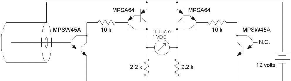
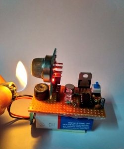
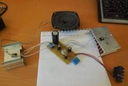
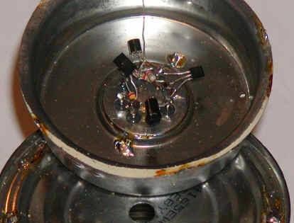
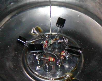
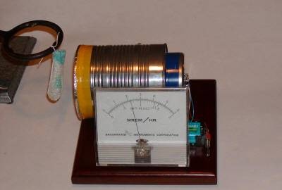
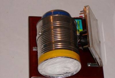
This looks a little confusing, but is actually quite easy to do. The circuit was assembled in the same tin as used in one of the JFET projects described above, and all parts of the circuit were mounted on an 8-pin circuit board. The astute reader will notice that I actually used 2.4 kOhm and 5.6 kOhm resistors, but these differences in values do not make a big difference.I also used a blocking capacitor connected in parallel with the battery, with a value of, for example, 10 uF. The sensor wire is directly connected to the base of the transistor and passes through a hole drilled in the bottom of the tin can. The circuit is quite sensitive to electric fields, so having a circuit wrapper like this is a good idea.
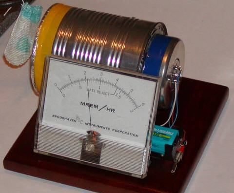
Allow the circuit to “warm up” for a few minutes after applying the supply voltage, after which the ammeter reading should drop to very low values. If the ammeter reading is negative, switch the sensor wire to the base of another transistor and reverse the polarity of the ammeter connection. If there is a noticeable voltage drop across the 2.2k resistors, maybe up to one volt, try cleaning everything with solvent and drying it completely. When the ammeter reading becomes low and stable, bring a radioactive source, such as a glow grid, to the foil-covered window and the reading should rise quickly. As a measuring device, you can use a digital voltmeter with a scale of up to 1 V or an ammeter with a scale of 100 μA. The meter shown below already has a scale graduated in units of radioactivity, and the reading of about 2.2 is due to exposure to the incandescent grid.
This is a simple sensor considering its sensitivity! An active experimenter might try other transistors, most likely compound ones such as the MPSA18, or even a voltage-controlled current op-amp such as the CA3080 with open-loop feedback.
]