There are various instructions on the Internet for turning an old (sometimes partially non-working) TV into a widescreen oscilloscope. This article will also tell you how to create a decent electronic device using simple modifications for a total cost of about $20. In order for the input signal to be displayed on the screen and reproduced through the TV speaker, you will need to assemble a simple device that switches the power supply circuit of the deflection system. Of course, you cannot stretch out a large frequency spectrum with such a device (actually 20-20,000 kHz), but monitoring low-frequency oscillations is quite accessible.
Watch the video
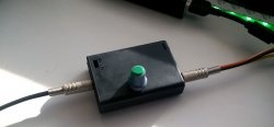
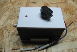
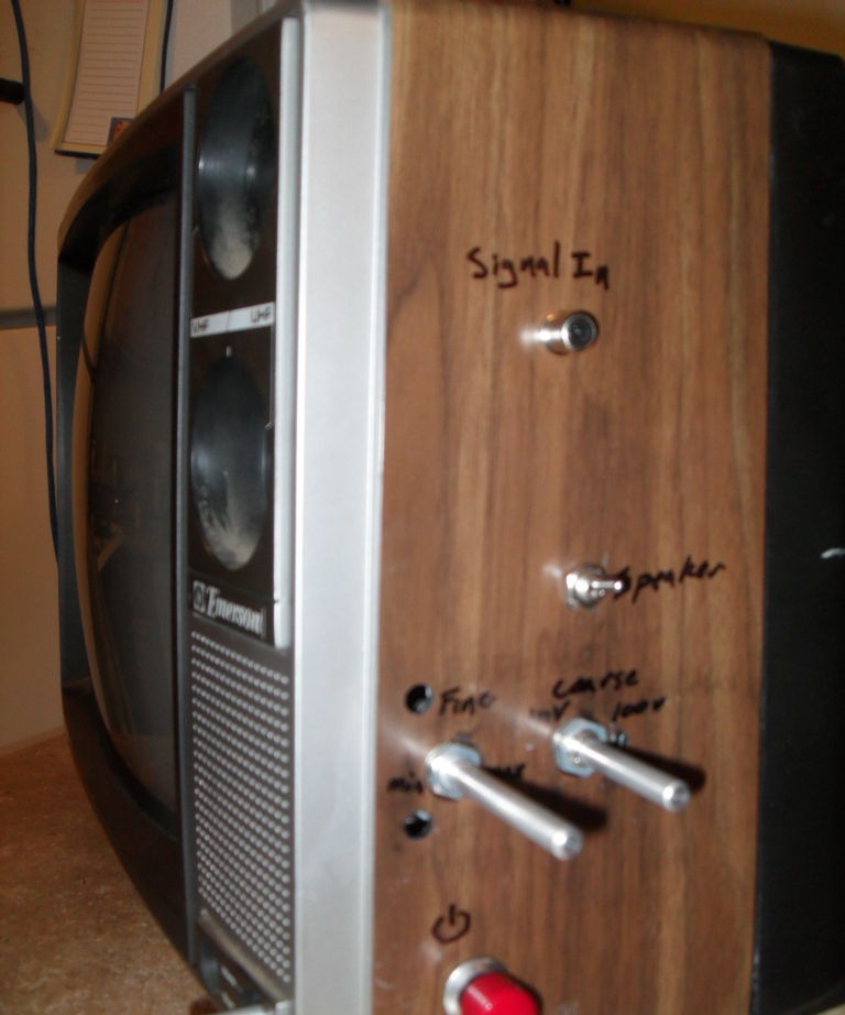
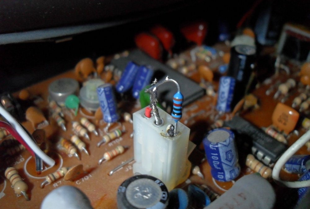
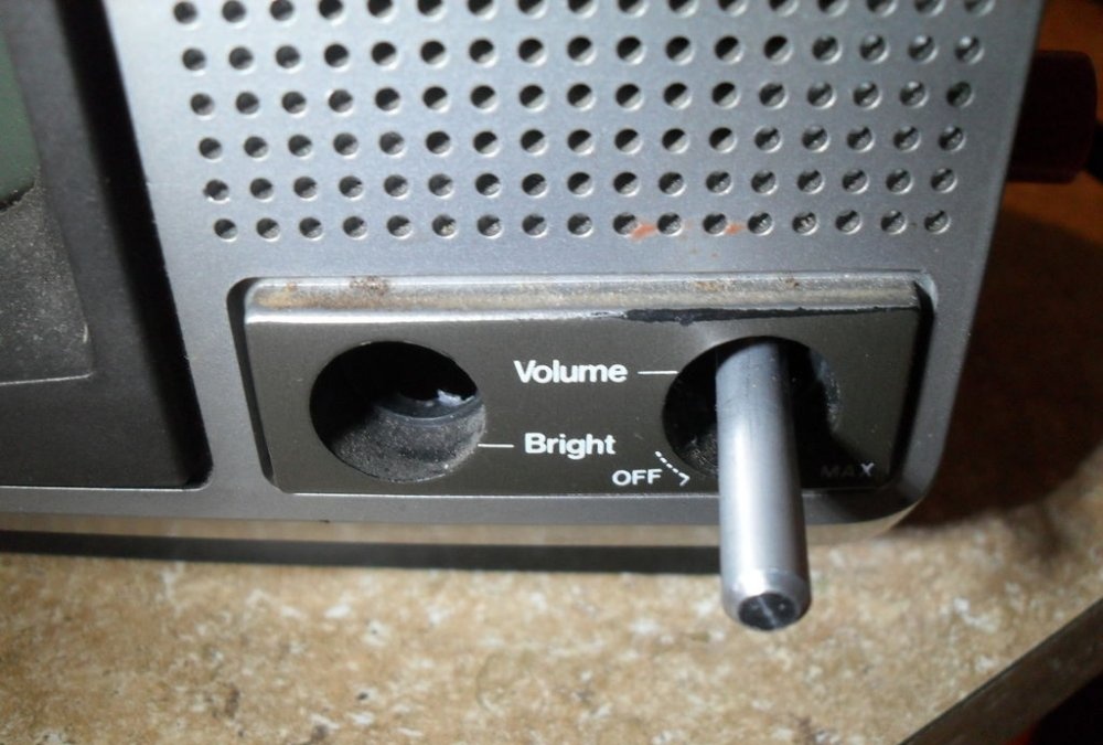
You can also install the main connectors and controls of the device into the television case (fortunately, the space allows this). For example, the presence of an RCA connector will be an excellent way to connect an iPod and at the same time allow the supply of alternating voltage signals from millivolts to hundreds of volts. Nearby you can place a 1 mOhm trimmer and a 6-section rotary switch. A small trimmer will be convenient to control the horizontal scanning frequency, and a bright red button is suitable for turning on the device.
It remains to add that this connection diagram is not suitable for all TV models and is more useful for people who know how to handle circuitry and have experience in electronics. But the idea itself contains many interesting points.
Safety requirements
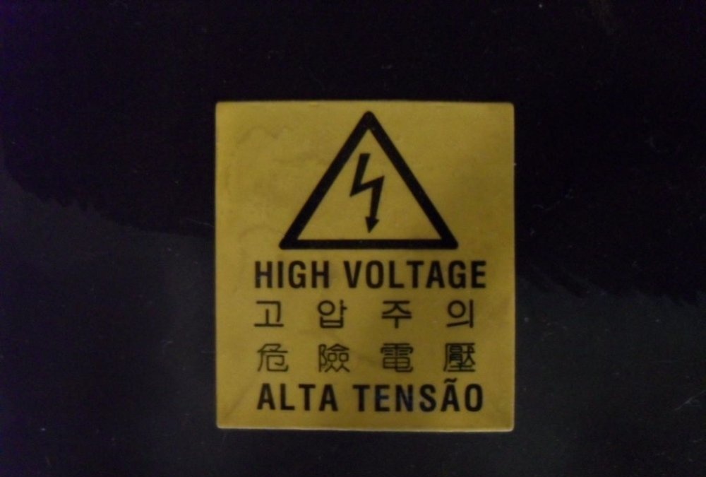
The implementation of the described project involves carrying out work near an open television transformer and high-voltage capacitors. The voltage at the magnetron reaches 120 kV! To eliminate the possibility of fatal electrical shock, proper safety precautions must be strictly followed. The first step to performing any action should be to completely de-energize the device. Here we must not forget about high-voltage capacitors. Therefore, the protective casing of the high-voltage unit is removed extremely carefully. It is important not to damage the wires of the printed circuit board or touch its exposed contacts.
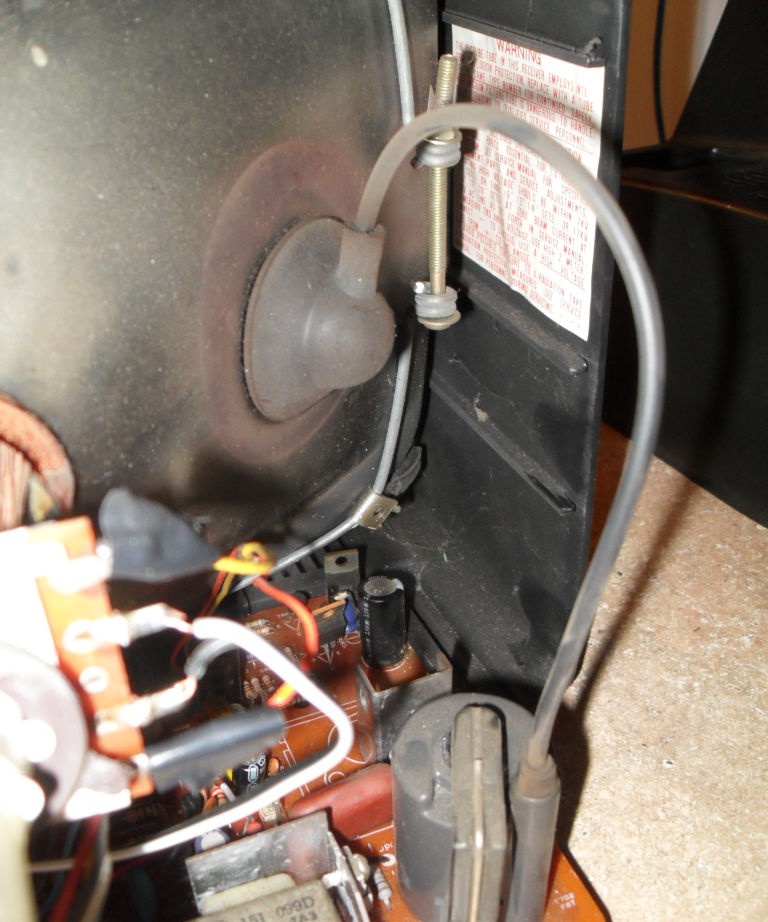
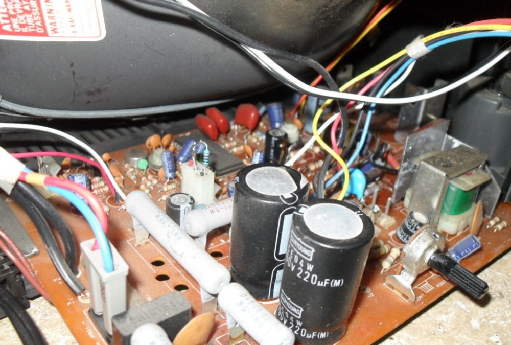
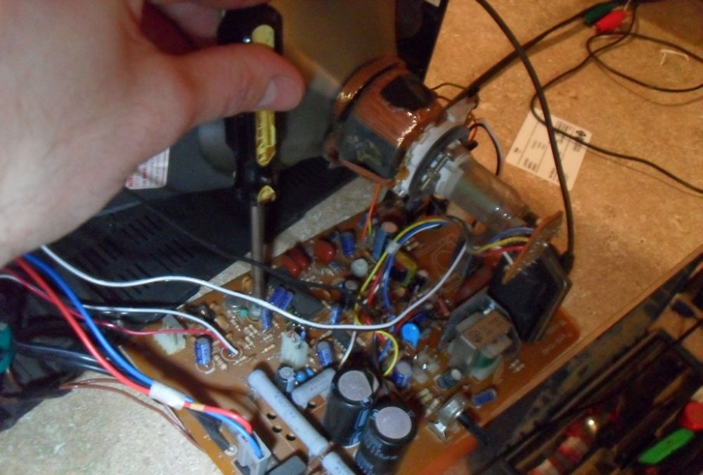
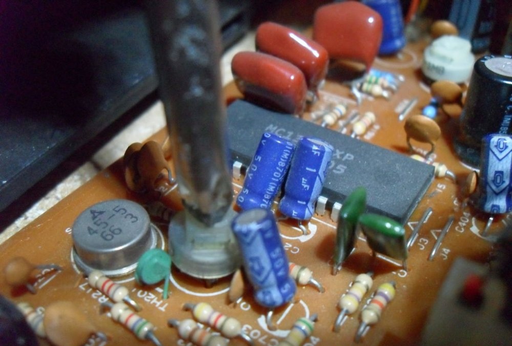
Next, you need to forcefully discharge large capacities (50 V or more). This is done with a well-insulated screwdriver or tweezers. Their contacts are closed to each other or to the housing until completely discharged. You should not do this on a printed circuit board, as the tracks may burn out. When performing work or testing the device, make sure that someone close to you is nearby who can call a doctor or provide first aid.
Principle of operation
Cathode ray tube (CRT) televisions and oscilloscopes are considered the most interchangeable devices. Also, a television receiver is more complex than a basic laboratory oscilloscope. To remake it, it is enough to get rid of some of the TV functions built into it and add a simple amplifier. After all, each unfolded line of the TV screen is created by an electron beam, quickly scanned through the transparent material of the luminescent substrate of the tube.
The charged electrons are controlled by electric and magnetic fields created by coils located behind the tube. These wire cores deflect the beam horizontally and vertically, controlling the placement of the image on the screen. To adjust it to the center of the oscilloscope line, it is necessary to make some modifications to them.
Let us remember that the video signal produces 32 frames per second, each of which consists of two “interlaced” images (that is, 64 frames are scanned). The NTSC standard defines 525 lines in the screen format, other standards have slightly different values. This means that to reproduce a filled picture on the screen, the electron beam must be deflected vertically every 1/64 seconds (frequency 64 Hz), and horizontally 1/(64x525) seconds (frequency 32000 Hz). To ensure such values, the voltage of the line transformer exceeds 15,000 volts. In this case, the device works like a TV and creates a detailed image on the screen.
To get it to draw an image on a very thin line vertically deflected by the input signal, you need to adjust the number of turns of the screen coils. It is also important to “work” with the inductor coil. Its impedance depends on frequency. The higher the frequency, the more difficult it will be to display it on the screen. With an outer diameter of the toroidal core of 10 mm and a thickness of 2 mm, windings I and III should each contain 100 turns of PELSHO 0.1 wire, and winding II should contain 30 turns.
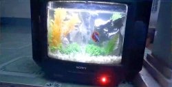
It’s also worth remembering that the signal on a TV is mathematically integrated. This causes the input square wave to appear as a triangle wave on the screen, and the input triangle wave as a sine wave. This only applies to the image, not the sound. Sine waves will be displayed without distortion.The phenomenon will not be as noticeable on very old TVs that are capable of displaying white noise or a blue screen when there is no signal, rather than automatically turning off the image.
Removing unnecessary nodes
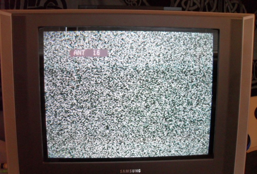
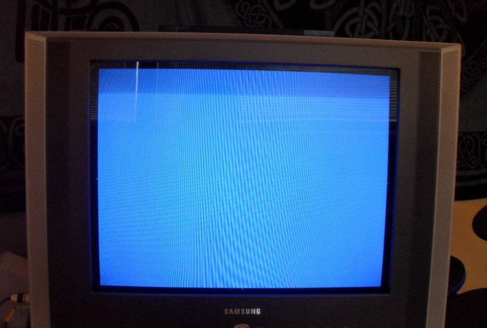
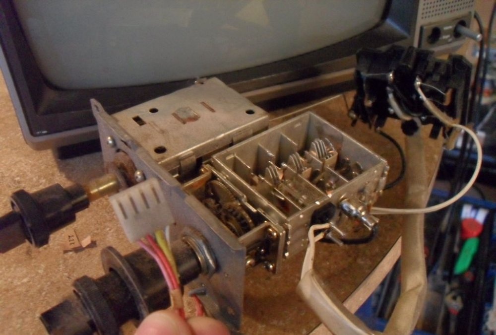
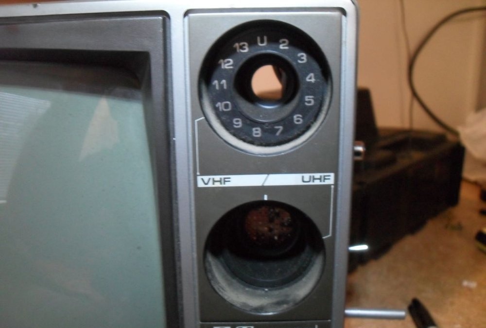
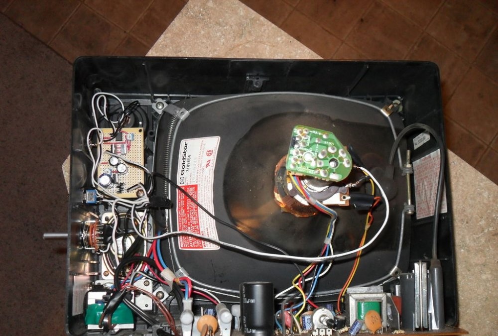
In our case, we used an old television receiver with a 15-inch screen and a classic UHF/VHF tuner. It is not required to create an oscilloscope, so you can immediately remove the tuner and forget about its existence. You can also gradually disconnect unnecessary modules one by one, checking that the TV can still function. You only need the main board and everything connected to the kinescope. It is necessary that it only displays white noise or a blue screen. You can simply empty the box of the remaining parts.
The TV being converted had two potentiometers on the front. One of them served to turn on and adjust the volume, and the other controlled the brightness. Both were removed: the first was replaced with a power switch (big red button), the second had to be set to maximum brightness and fixed by soldering additional resistors into the circuit. You should immediately note that a device with a built-in volume control is not suitable for modification. It amplifies the signal attached to the television and you will have to look for an amplifier on the main board, and this will cause additional problems. The speakers can also be turned off at this stage.
Preparing the deflection system
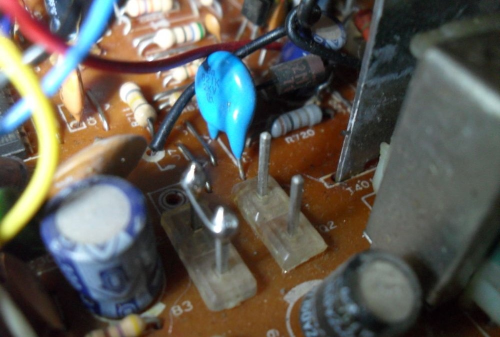
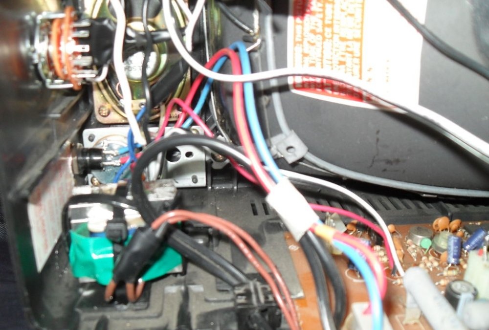
To achieve an oscilloscope image on the kinescope screen, you will need to apply the generated amplified signal of vertical and horizontal sync pulses to the deflection coils H and V. How to obtain it will be discussed a little later, but now it is necessary to prepare the deflection system.The coils are connected to the main board with four pins. You need to disconnect the horizontal one, the red and blue wires go to it. By connecting an iPod or computer directly to these terminals, you can display music on the kinescope screen. The vertical coil has a yellow and orange wire, but to get a 64Hz scan they need to be switched to the horizontal coil.
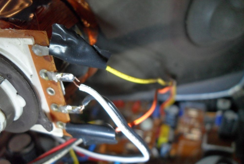
Now you need to find where the coils connect to the small circuit board on the picture tube tube. If the television receiver is not very new, there are only two coils and 4 wires go from them to the main board. Otherwise, there will be more coils and the modification will not work in this form. But don’t give up what you started, and you can experiment a little. For now, we will assume that there are still 4 wires. It remains to deal with the wires going to the kinescope. According to the right-hand rule (F=qVxB), we remove one of them in random order. If, when you turn on the device, a horizontal line is displayed on the screen, the vertical coil is disabled; if it is vertical, then vice versa. The corresponding ends are found by the tester and marked.
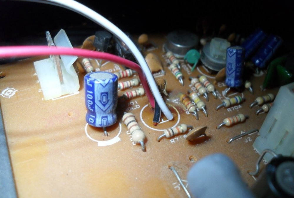
The horizontal coil connection wires are now removed from the main PCB. Do not forget that you will have to deal with a frequency of 30,000 Hz and a voltage of more than 15,000 volts. The future oscilloscope does not need them. Before touching, they must be short-circuited, then well insulated and placed inside the case so that they do not touch anything after turning on the device. So, the 60 Hz vertical marking line is ready. To obtain the same horizontal line of 60 Hz, we solder the two remaining wires going to the vertical coil to the horizontal one.And the vertical one will become the input of the oscilloscope for connecting the amplifier circuit.
Sweep setting
The further part of the work is the most dangerous, since it will be performed with the voltage connected. Be especially careful! We try to connect the signal source to the vertical deflection coil (this could be an MP3 player or a computer headphone output). To display one frequency on the screen, try to generate a consistent tone. With the TV turned on, use an insulated screwdriver to carefully touch the high-voltage wires one by one, finding out what changes on the screen this will lead to (your assistant should watch this or use a large mirror).
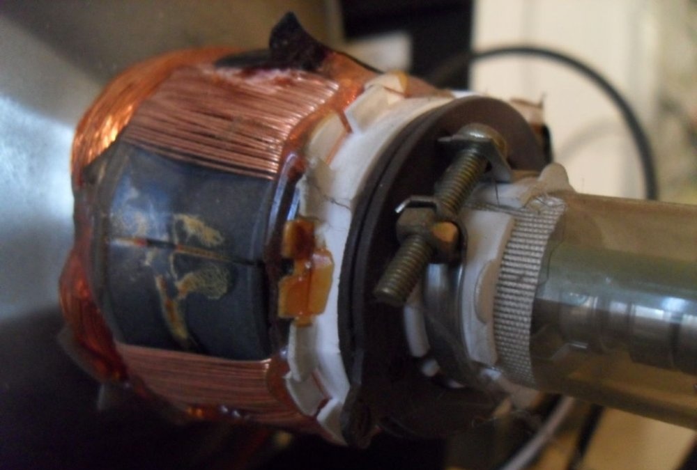
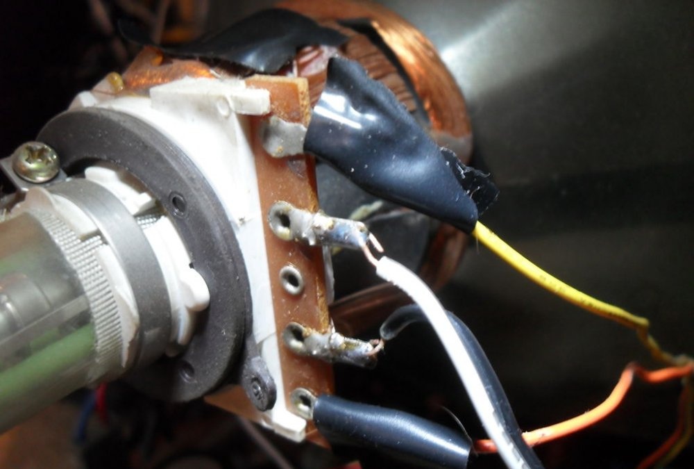
One of them will affect the scanning frequency. On the board where it enters, you need to solder a trimmer resistance (approximately 50-60 kOhm). After making sure that the unit is working, you can remove the handle of the involved resistor from the device body. Even an impeccably executed horizontal frequency tuning will not allow you to see the upper range, but will only display the scroll waveform on the screen. You can also customize the existing ring tabs located around the narrow part of the kinescope tube. They are usually black or dark gray in color and also indirectly control the final image.
Incoming signal amplification
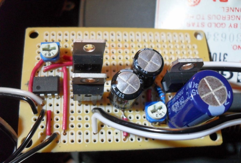
Everything that has been done up to this point has allowed us to create a good input signal visualizer. It is enough to connect the iPod socket to the vertical deflection coil and the sounding music will be displayed on the screen. But to get a real oscilloscope, you will need an additional amplifier (you can assemble it where the discarded UHF/VHF tuner was located).His idea was borrowed from several thematic sites in order to obtain minimum cost and maximum efficiency. The design of Pavel Falstad was taken as the basis, and the presented printed circuit board is a modified circuit of a push-pull audio amplifier.
To implement it we will need: a TL082 microassembly, including 2 op-amps, a pair of transistors (for example, 41NPN/42PNP), an LM317 power regulator, a Pole rotary switch, a 1 mOhm potentiometer, two 10 kOhm trimers, 4 1A diodes, a transformer for 30 VAC, 1000 µF 50 V electrolyte, two 470 µF 16 V electrolytes and 5 resistors (10 Ohm, 220 Ohm, 1 kOhm, 100 kOhm and 10 mOhm).
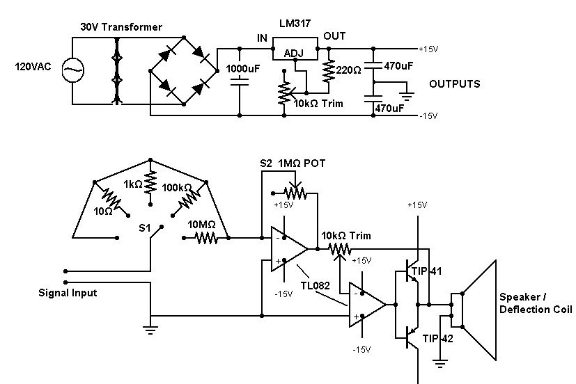
The first op-amp controls the gain of the input signal using the formula R1/R2, where R1 is the resistance selected by the rotary switch, R2 is the 1 mOhm pot. Theoretically, it is capable of amplifying the input signal up to 1 million times (with a minimum of 1 ohm present on the rotary switch). The second monitors that the transistors receive the necessary voltage to open the junctions and compensates for distortions. They need 0.7 V to open and 1.4 V to switch.
The finished circuit requires mandatory calibration. The power regulator is designed for a difference of 30 V, so the op amp will typically output +15/-15 V, but for good filtering its output should be a few volts lower than the voltage across the 1000 uF capacitor. For this purpose, there is trimmer 1. The output of the circuit is connected to the horizontal deflection coil. Music passed through the circuit begins to be “cut off” at the top/bottom. To avoid this, trimmer 2 is adjusted until the tops of the clips touch the edges of the screen. This will lower the voltage and prevent the transistors from overloading the RF path of the device (burning the deflection coil).
Now you can connect the built-in speaker system to the TV output. If the volume is excessive, a large load resistance is added (for example, 10 Ohm 1 W); if there is insufficient sound, the load resistance is placed on the deflection coil, after which the latter is recalibrated. To protect yourself from unnecessary annoying beeps while scanning for the desired input signal, you can install a switch on the speaker.
Putting it all together
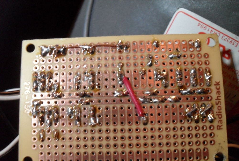
An additional amplifier can generate a strong magnetic field, so it is worth taking care of its design. The board should be made as compact as possible, with short leads and good grouping. It does not require special shielding, but to avoid interference with other TVs in your home, make sure that it is located in the case without creating interference to the main components. As a last resort, you can use a wooden or plastic case covered with foil on the inside.
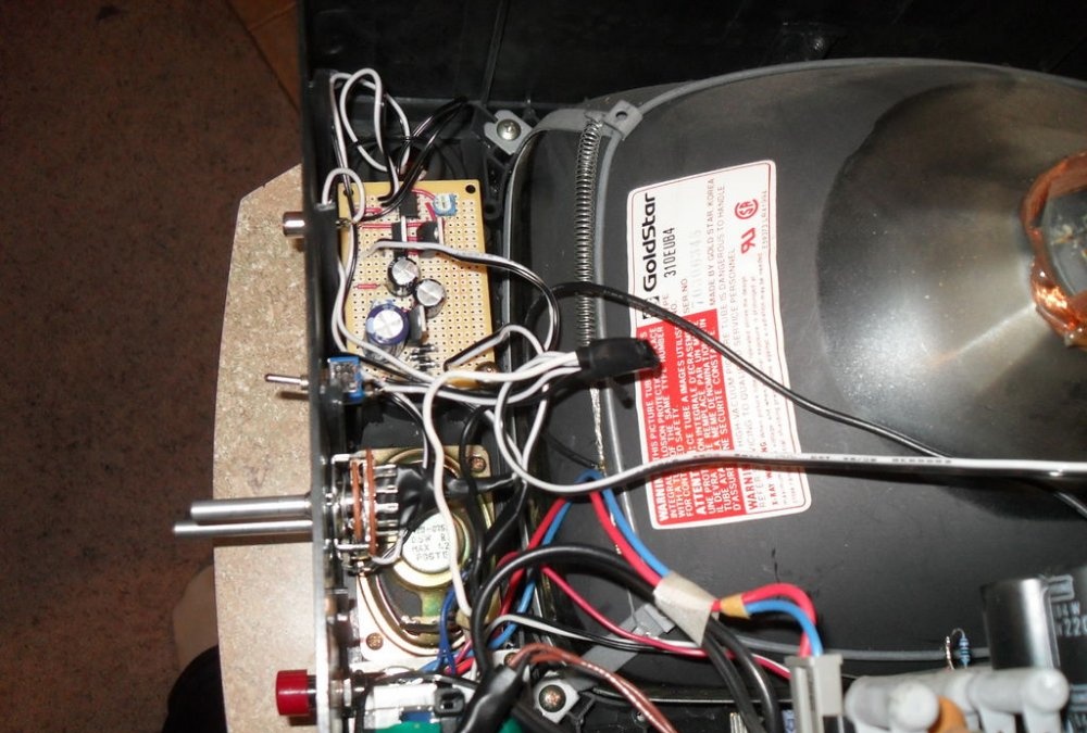
In the TV being disassembled, when removing the analog tuner, enough space was freed up to install a transformer with such a board, and there was even a hole for the power switch. It is also advisable to shield the transformer so as not to create interference on TV channels. Connect the terminals for connecting the synchronization voltage and the signal under study to the board only with a shielded wire.
After connecting the transformer to the circuit, connect S1 and S2 respectively, run the input wires through the hole in the body of the television receiver, connect the output of the circuit to the speaker and deflection coil. A minimum wire length should be used in all connections made to reduce leaky loop inductance.All that remains is to find a convenient place to install S1 and S2, close the back cover and start the test drive.
Checking the functionality of the device
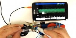
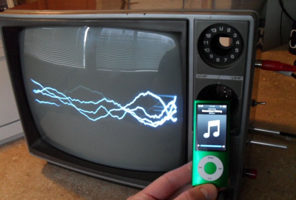
In terms of functionality, the assembled oscilloscope is far from worthy laboratory models, but is indispensable for use in simple projects where you need to see the waveform. Also a certain novelty is the ability to hear the signal being studied, especially when receiving feedback that resembles “signs”. In the example under consideration, one can observe a change in the signal induced by a conventional wire coil when it is located in an arbitrary location, above the internal transformer of the device and when it is located above the laptop processor.
The ability to amplify the incoming signal is a great feature if you don't need it to be absolutely precise. The 60 Hz noise amplified by the circuit can still be detected with reasonable accuracy. But this phenomenon is also caused by the stray inductance of the input wire. Only shielded grounding of all parts of the circuit can reduce interference.
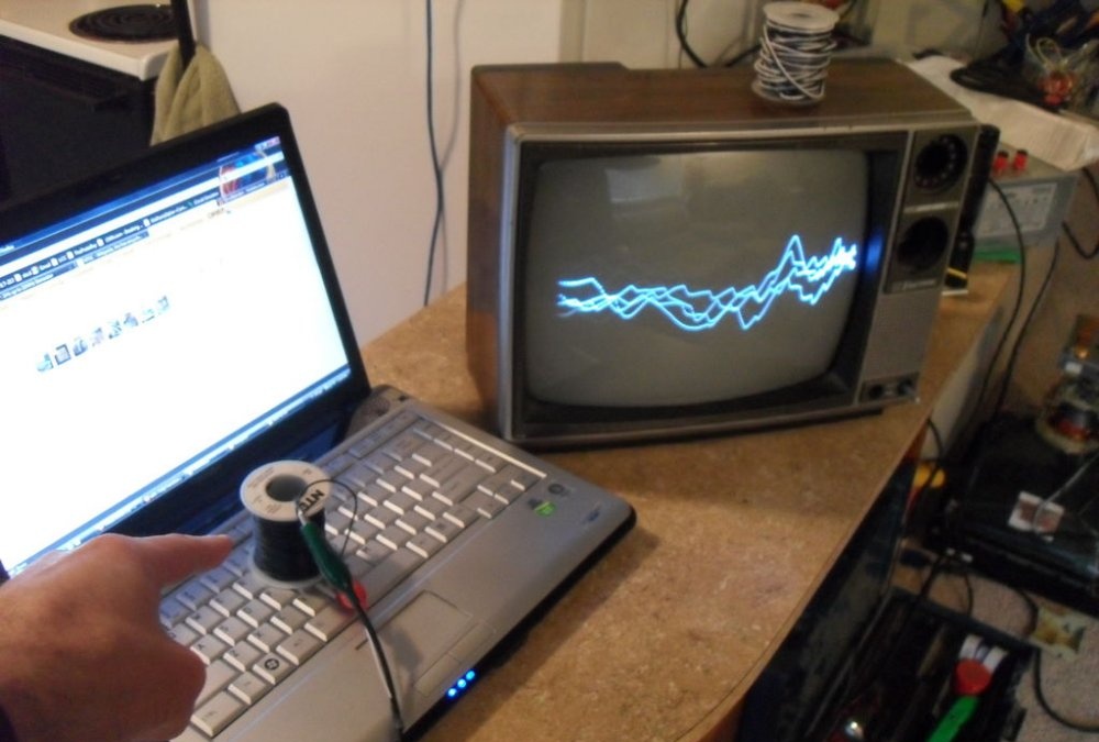
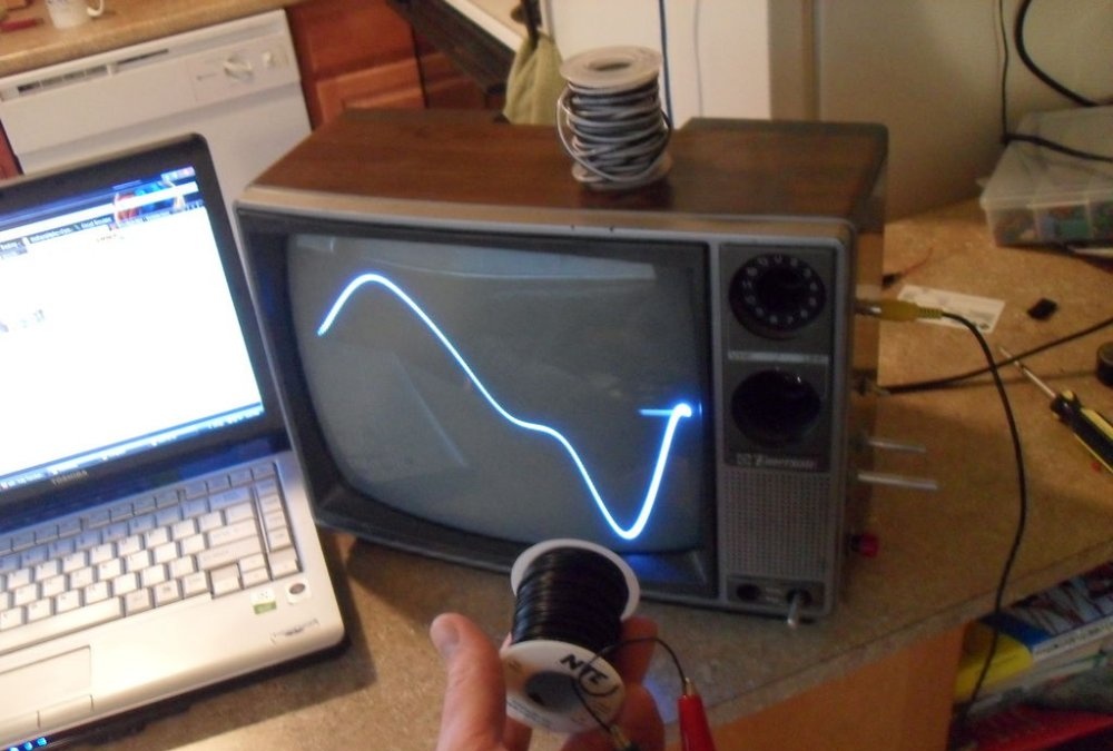
The demonstrated coil of wire connected to the input of the device allows the use of large inductance with high amplification. It can detect power sources several meters away by pointing the coil towards the location of the transformers, and then visually view their operation. You can also detect the location of the processor inside a complex device. You can use the coil as an inductive microphone by placing it near a speaker playing music. The magnetic field reproduced by the speaker coil will be detected and amplified by the created device, after which the music being played will be reflected on the oscilloscope kinescope.
You can clearly view the operation of the Internet channel on the device.A dedicated home line (120 VAC) was used as an input signal for this, and, having shown its “picture”, the device still works.
Original article in English