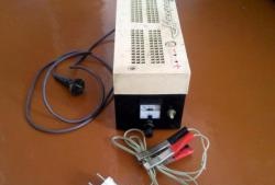
When you repair a computer power supply or perform modifications, you need to constantly take voltage measurements. It is also sometimes necessary to measure resistance using output voltages. I decided to assemble an adapter device between the power supply and the multimeter. With such a device, your hands will always be free and the work will go faster. This unit can also be used to power low-power devices. The current is limited by the operating current of the switch.
Scheme
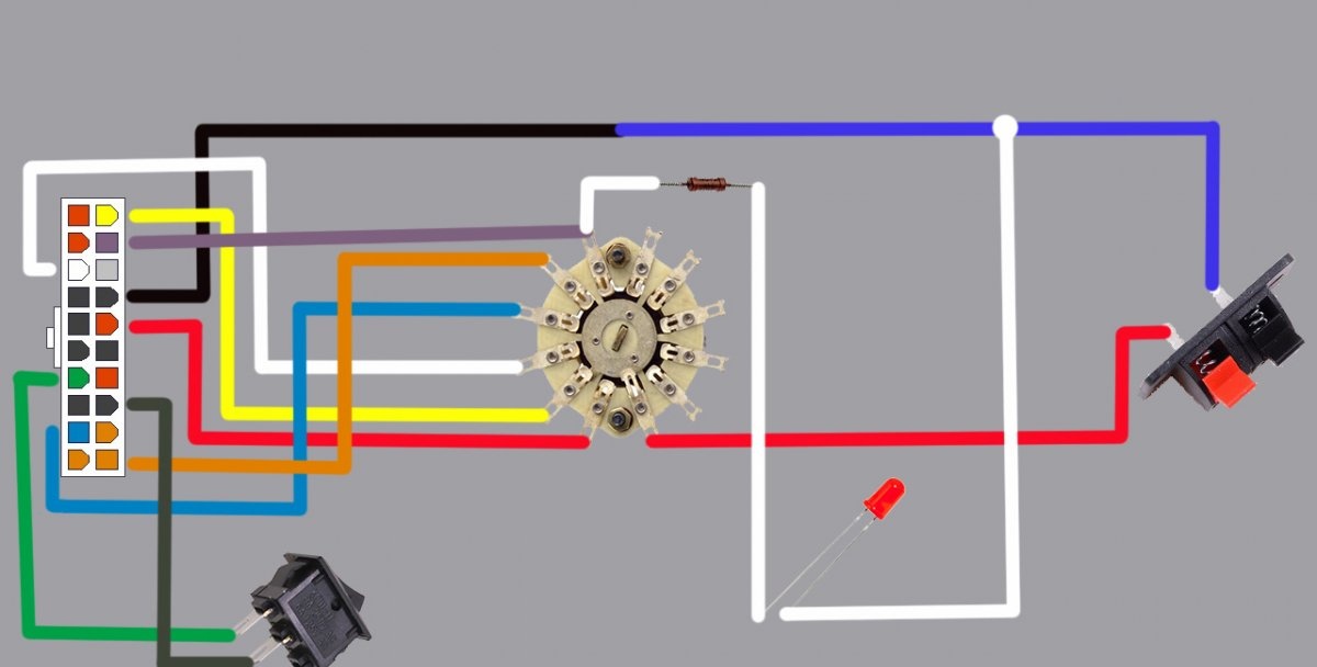
The circuit diagram of the device is simple and assembly is not difficult.
The input voltage comes to the 20-pin connector, and the output voltage is removed from the terminals. All voltages are switched by a roller switch. There is an indication of the operation of the computer power supply. Feeds Light-emitting diode indications from the attendants 5 Volts. The computer power supply is started by a switch.
Making the switch
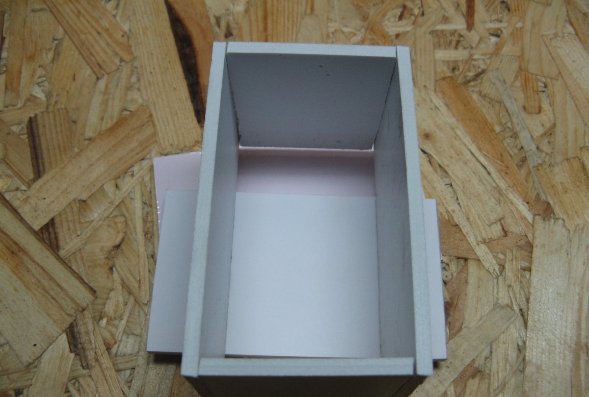
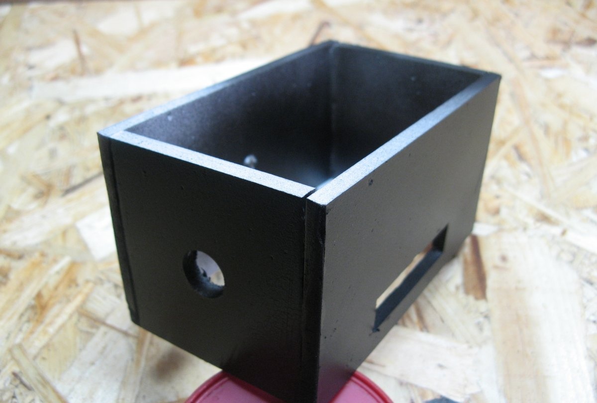
The device can be mounted in any suitable housing. I will make the housing myself. I will make it from PVC plastic.The plastic was collected from advertisers, the scraps of which are thrown away.
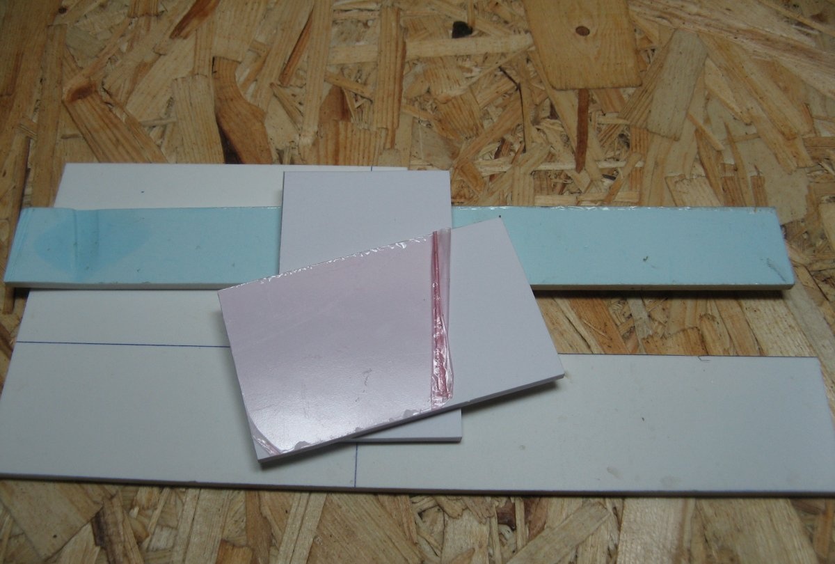
We cut out the necessary parts of the plastic and glue them with super glue. It looks like the letter “O”. You also need to cut out the front and back panels.
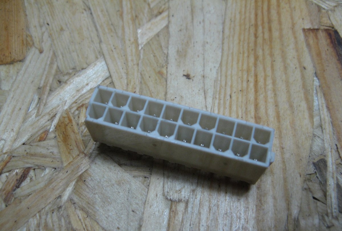
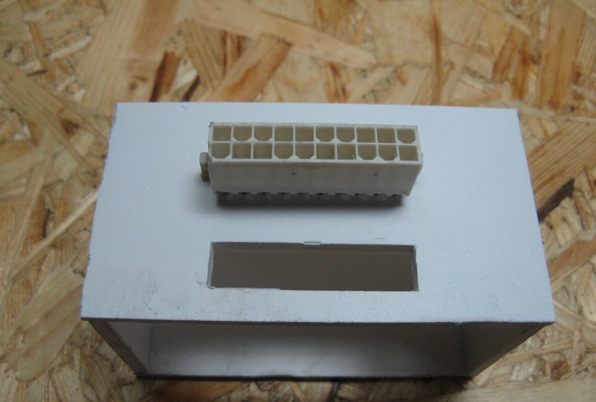
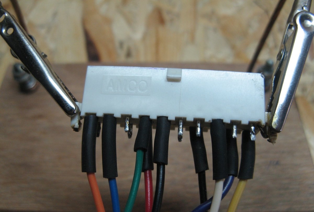
The computer's power supply is connected to a 20-pin connector. I unsoldered it from the old motherboard.
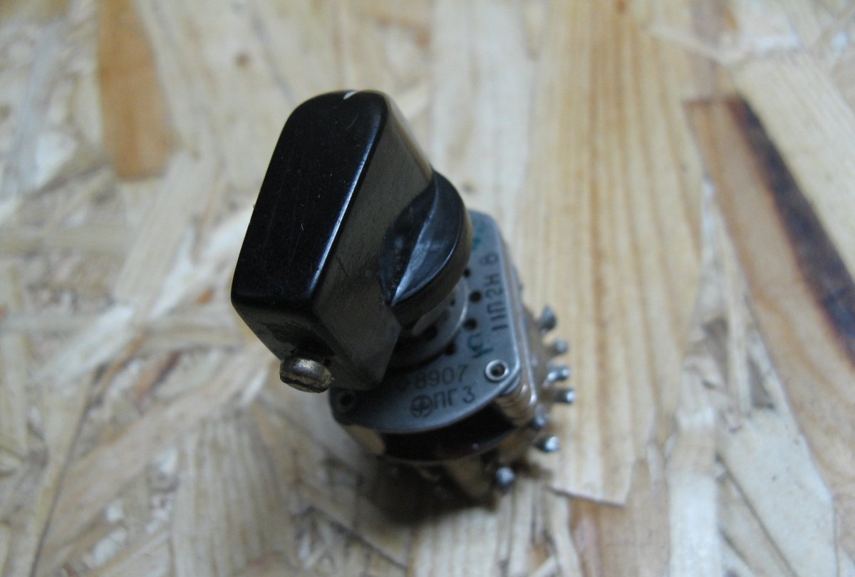
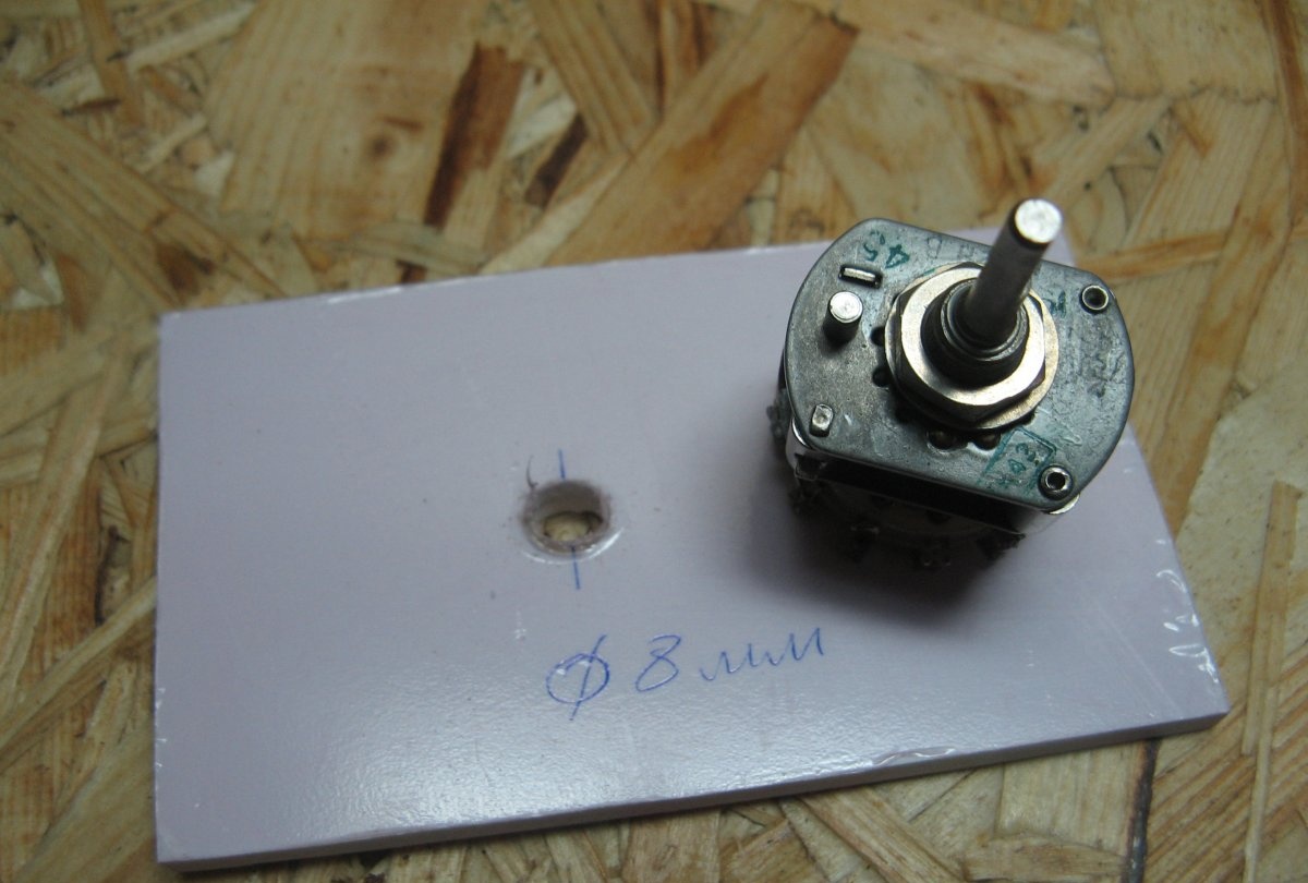
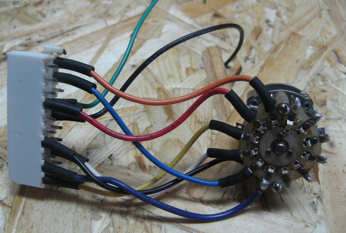
I will switch the output voltage using a PG-3 biscuit switch. If you can get a 6-position switch, then great. I have 11 positions, but it is what it is. There was also a handle for the switch.
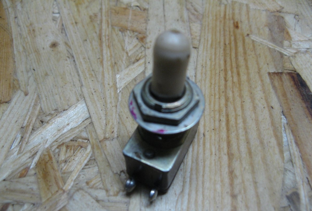
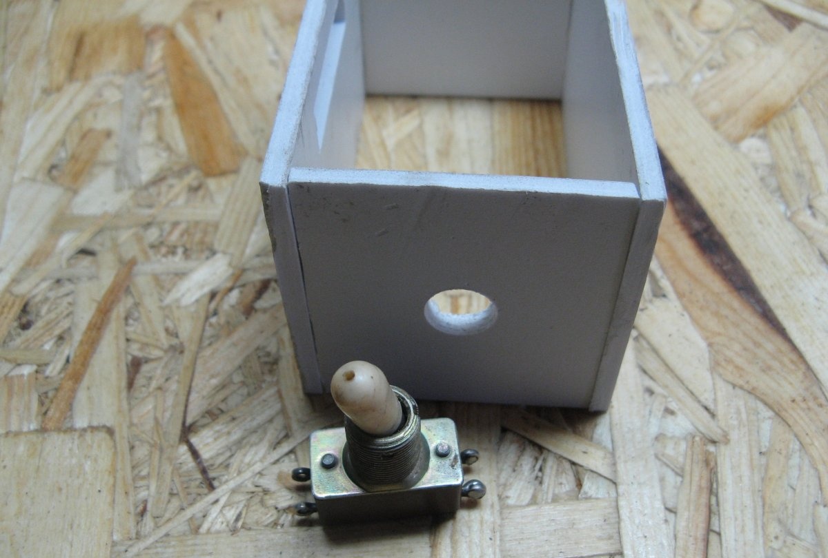
You can turn on the power supply using any switch. I have a switch from an old TV.
On the front panel we drill holes for the biscuit switch. Diameter 8 mm.
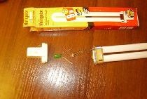
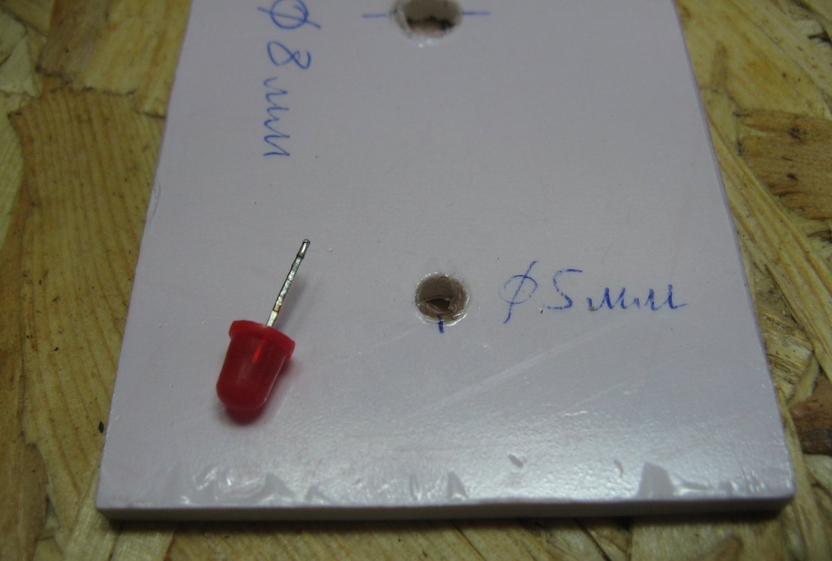
The connection indicator will be Light-emitting diode. To limit the current to Light-emitting diode you need a resistor, you need it at 150 ohms.

Drill a hole for Light-emitting diode. Diameter 4.5 mm, under Light-emitting diode 5 mm. This will make it install more tightly.
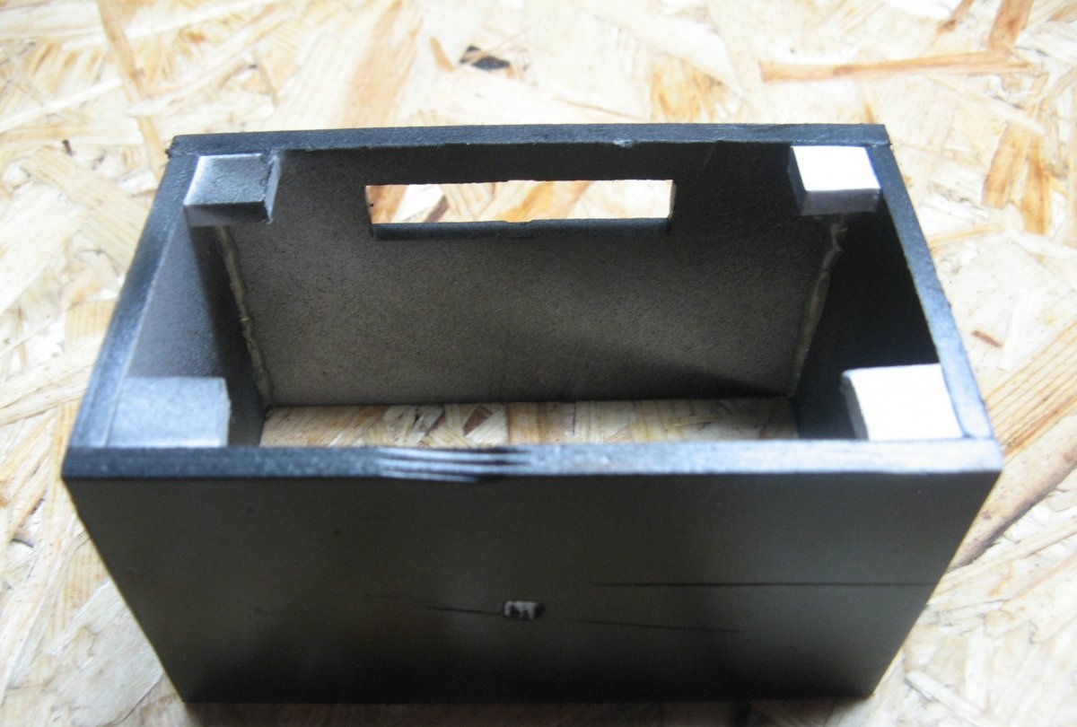
We cut a hole in the side wall for the connector.
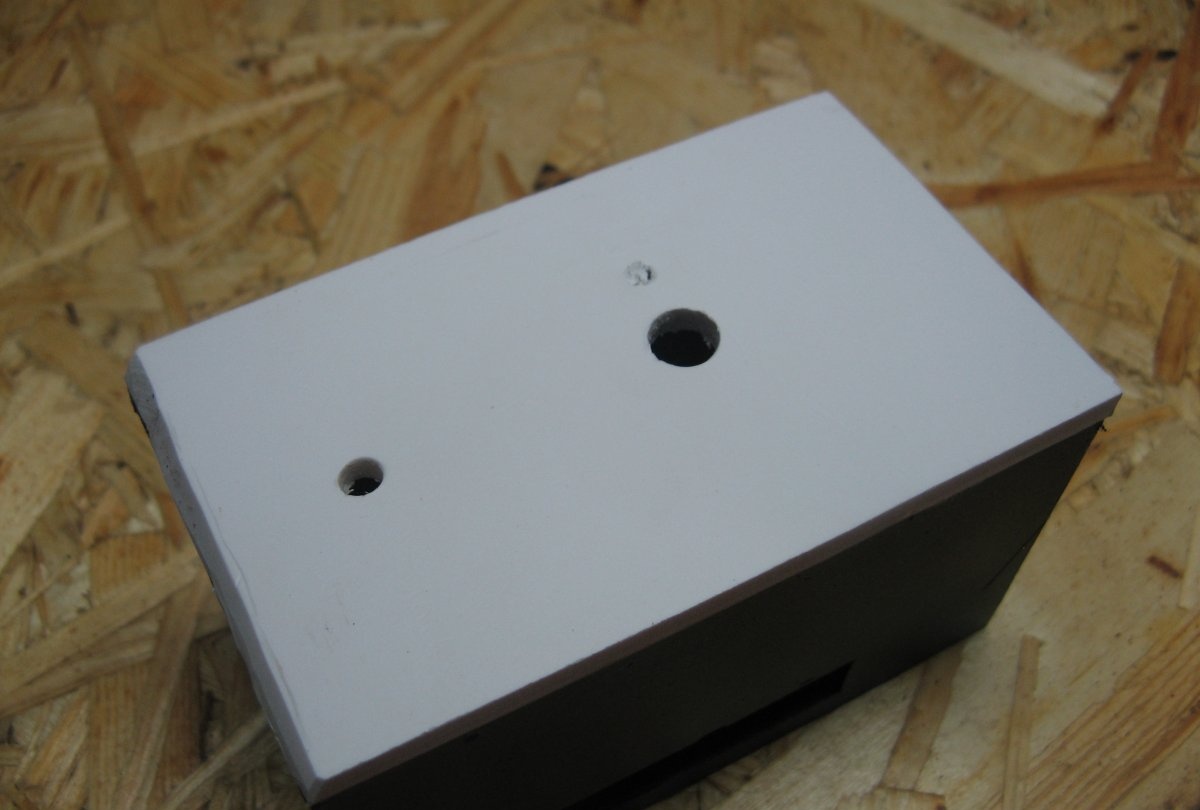
We drill a hole on top of the case for the switch. Diameter 12 mm.
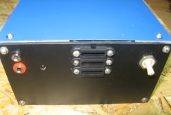
At this stage I have not decided on the terminals for connection multimeter. So I painted the body black and will drill the holes later.
After the paint dried, I still drilled one hole. You can see it in the photo.
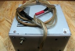
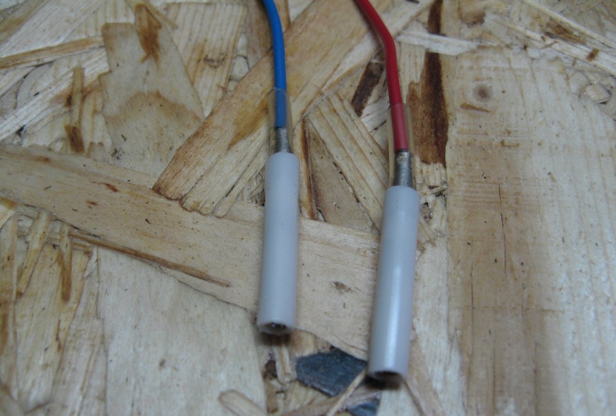
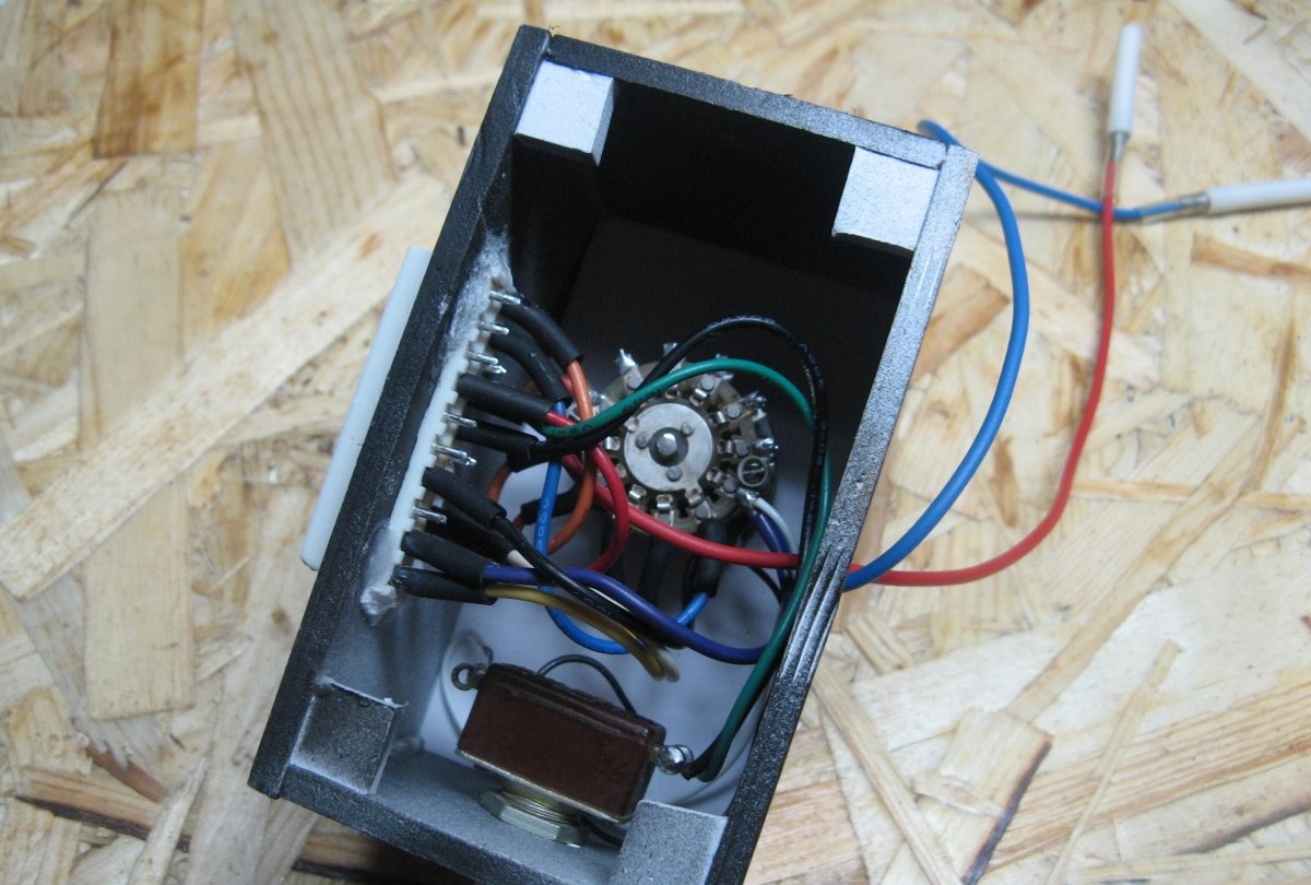
For removable terminals I will use sockets from the military connector ШР. I immediately soldered the wires to them and insulated them.
The front panel will be glued with super glue, and the back panel will be screwed with small screws. To screw in the screws, I will glue backings made of the same plastic as the body. I glue it with super glue.
I glue the front panel.
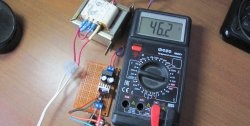
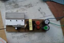
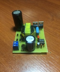
I'm putting the case aside for now and moving on to wiring the circuit. Everything is soldered according to the sketched diagram.It is convenient to connect the power supply connector and solder the wire colors accordingly. Soldering points must be insulated.
I solder the biscuit switch according to the diagram. Everything is simple and accessible.
Soldered the LED and switch. Now you can install everything into the case.
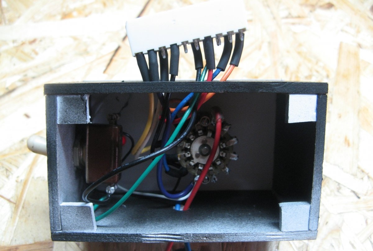
Glue the connector with super glue and soda. It makes excellent glue, almost like epoxy.
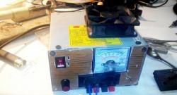
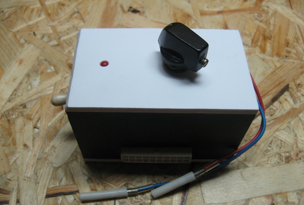
We screw the back wall and get an excellent design.
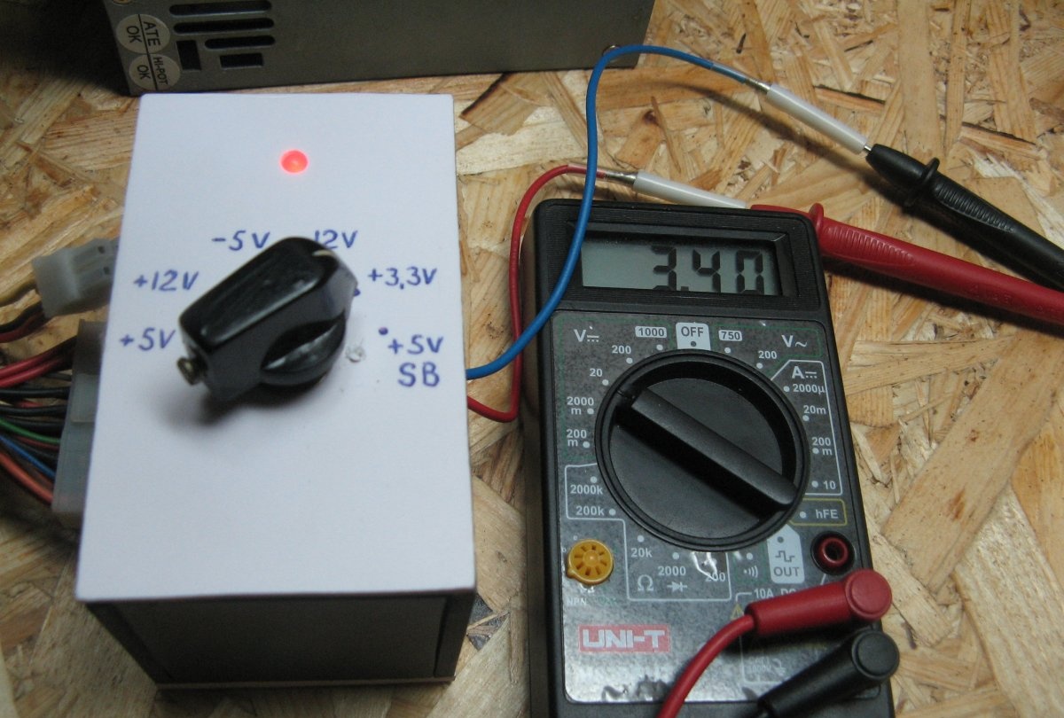
Check switches
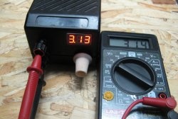
Connecting multimeter. Turn on the switch. We control the output voltage of the computer power supply. During the assembly process, I redid the sequence. It seemed more convenient to me. The standby mode is duplicated. The LED lights up and the last position shows 5 volts.