Do it yourself
Life hacks, master classes, useful tips, recipes.
home » Electronics » Simple circuits » Simple adjustable stabilized power supply

This power supply on the LM317 chip does not require any special knowledge for assembly, and after proper installation from serviceable parts, it does not require adjustment. Despite its apparent simplicity, this unit is a reliable power source for digital devices and has built-in protection against overheating and overcurrent. The microcircuit inside itself has over twenty transistors and is a high-tech device, although from the outside it looks like an ordinary transistor.

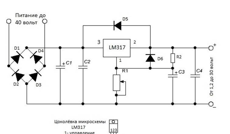
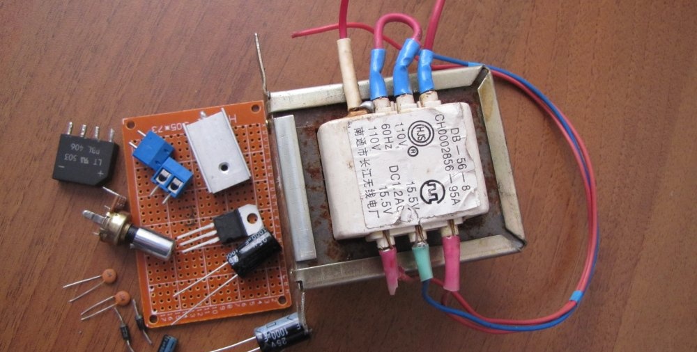
The power supply of the circuit is designed for voltages up to 40 volts alternating current, and the output can be obtained from 1.2 to 30 volts of constant, stabilized voltage. Adjustment from minimum to maximum with a potentiometer occurs very smoothly, without jumps or dips. Output current up to 1.5 amperes. If the current consumption is not planned to exceed 250 milliamps, then a radiator is not needed. When consuming a larger load, place the microcircuit on a heat-conducting paste to a radiator with a total dissipation area of ​​350 - 400 or more square millimeters.The selection of a power transformer must be calculated based on the fact that the voltage at the input to the power supply should be 10 - 15% greater than what you plan to receive at the output. It is better to take the power of the supply transformer with a good margin, in order to avoid excessive overheating, and be sure to install a fuse at its input, selected according to the power, to protect against possible troubles.

To make this necessary device, we will need the following parts:

  • Chip LM317 or LM317T.
  • Almost any rectifier assembly or four separate diodes with a current of at least 1 ampere each.
  • Capacitor C1 from 1000 μF and higher with a voltage of 50 volts, it serves to smooth out voltage surges in the supply network and the larger its capacitance, the more stable the output voltage will be.
  • C2 and C4 – 0.047 uF. There is a number 104 on the capacitor cap.
  • C3 – 1 µF or more with a voltage of 50 volts. This capacitor can also be used with a larger capacity to increase the stability of the output voltage.
  • D5 and D6 - diodes, for example 1N4007, or any others with a current of 1 ampere or more.
  • R1 – potentiometer for 10 Kom. Any type, but always a good one, otherwise the output voltage will “jump”.
  • R2 – 220 Ohm, power 0.25 – 0.5 watts.

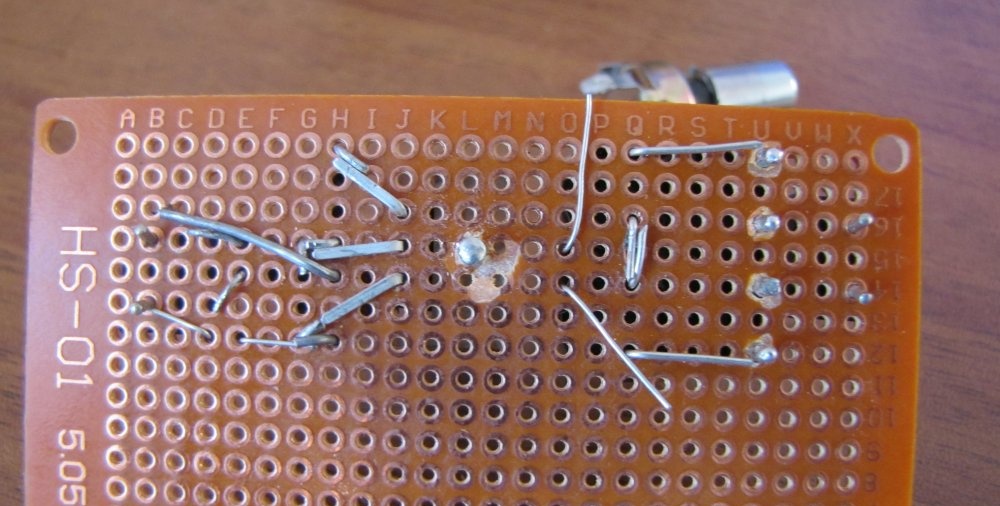
Before connecting the supply voltage to the circuit, be sure to check the correct installation and soldering of the circuit elements.

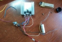
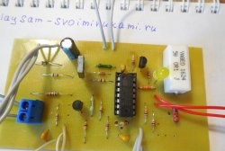
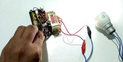
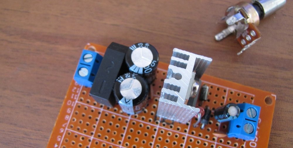
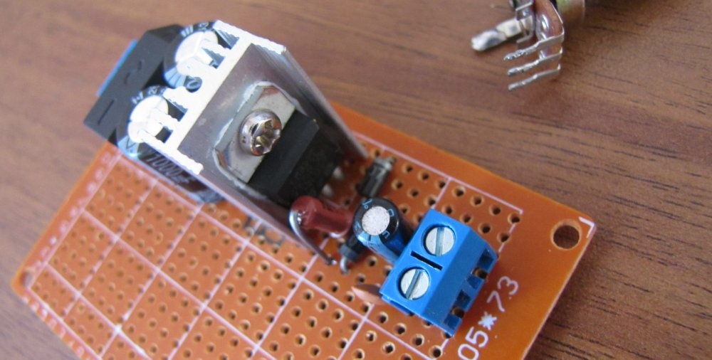
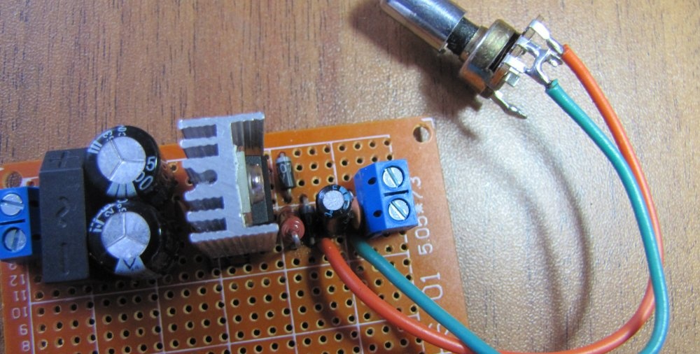
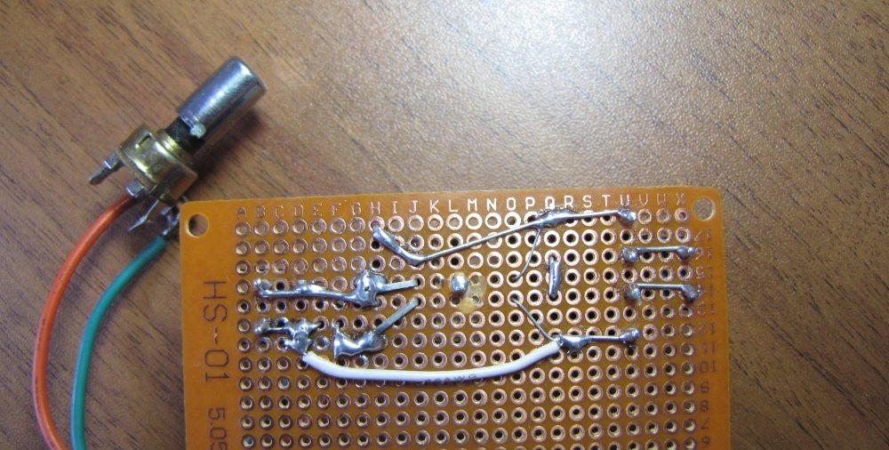
Assembling an adjustable stabilized power supply

I assembled it on a regular breadboard without any etching. I like this method because of its simplicity. Thanks to it, the circuit can be assembled in a matter of minutes.

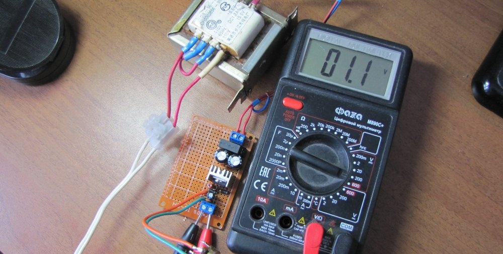
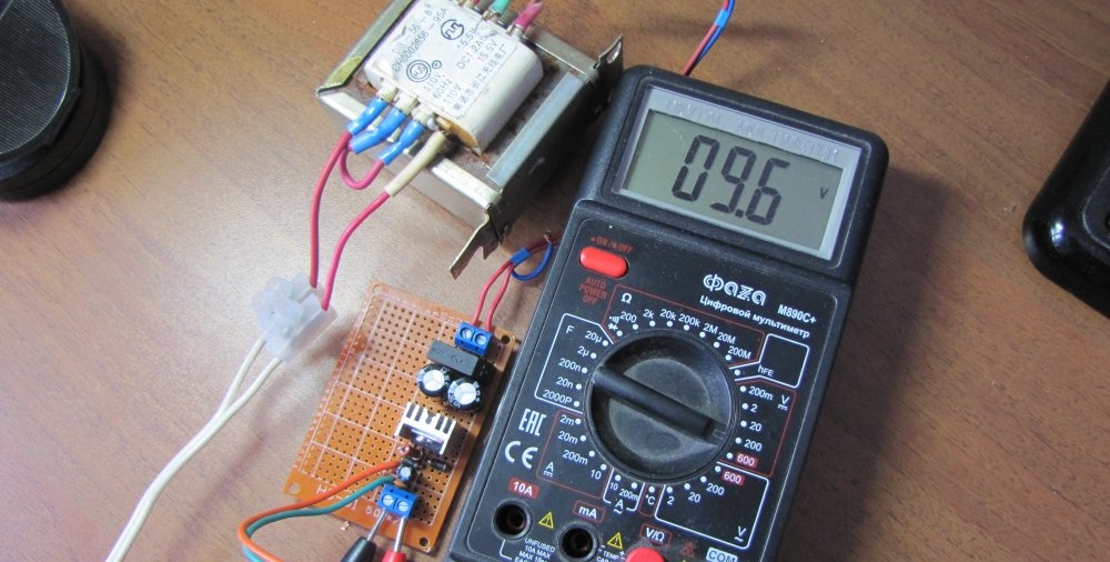
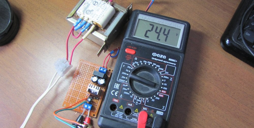
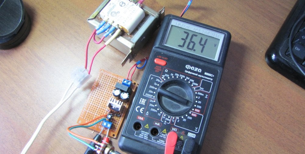
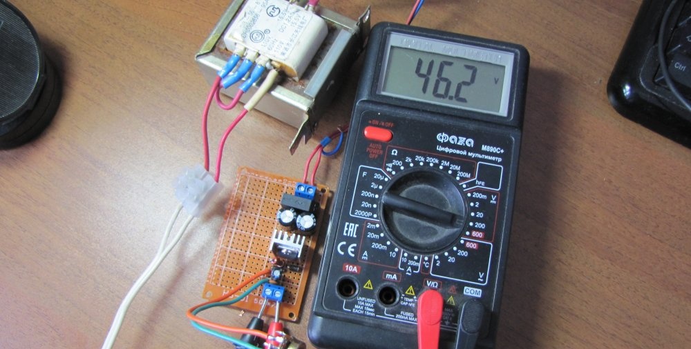
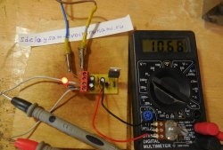
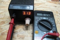
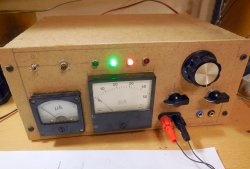
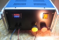
Checking the power supply

By rotating the variable resistor you can set the desired output voltage, which is very convenient.

Simple regulated stabilized power supplySimple regulated stabilized power supplySimple regulated stabilized power supplySimple regulated stabilized power supplySimple regulated stabilized power supply

Video of testing the power supply is attached

come back
Comment
  • bowtiesmilelaughingblushsmileyrelaxed relaxedsmirk
    heart_eyeskissing_heartkissing_closed_eyesflushedrelievedsatisfiedgrin
    winkstuck_out_tongue_winking_eyestuck_out_tongue_closed_eyesgrinningkissingstuck_out_tonguesleeping
    worriedfrowninganguishedopen_mouthgrimacingconfusedhushed
    expressionlessunamusedsweat_smilesweatdisappointed_relievedwearypassive
    disappointedconfoundedfearfulcold_sweatperseverecrysob
    joyastonishedscreamtired_faceangryragetriumph
    sleepyyummasksunglassesdizzy_faceimpsmiling_imp
    neutral_faceno_mouthinnocent
5+two=
Comments (10)
  1. Ivan
    #1 Ivan Guests January 23, 2018 10:49
    0
    Why do you need such a regulator!!! Where and how often do we use 40 volt voltage in regulated stabilized power supplies!!!????
    1. Dgek
      #2 Dgek Guests 23 January 2018 17:11
      2
      The answer is in your question. Adjustable. From 1.2 volts and above. Whoever needs what voltage, this is what you can get.
  2. Nik
    #3 Nik Guests 24 January 2018 16:40
    4
    It’s quite a good thing, I attached such a regulator to a screwdriver with a dead battery, so my wife winds the bobbins with it, it’s very convenient, because it doesn’t require much effort.
  3. Novel
    #4 Novel Guests February 11, 2018 09:41
    11
    Maybe c2 and c4 are marked not 104... but 473? Or 0.1 µF capacitance
  4. Guest Igor
    #5 Guest Igor Guests 7 June 2018 15:12
    2
    For what reason do chips connected without load and voltage of 30 volts burn out?
  5. Gallaxy dragon
    #6 Gallaxy dragon Guests November 9, 2018 07:40
    2
    Well, damn it... you tried to attach a phaser to the side of the 220 phase...
  6. Guest Victor
    #7 Guest Victor Guests 1 February 2019 18:51
    0
    Good evening

    I want to assemble this power supply to charge a csb battery hr1234w f2, and as a laboratory unit, but I want to add a power regulator, i.e. ampere:

    Instead of resistor R2, put a potentiometer?
    or take R2 with a lower value and put a potentiometer in front of diode D6?

    or add another LM317 microcircuit to the output and connect legs 1 and 2 with a 10-100 ohm potentiometer?

    ....

    Do you need a transformer from 20 to 40 volts?
  7. Guest Anatoly
    #8 Guest Anatoly Guests June 24, 2019 07:45
    1
    I tried it. The circuit is simple but works reliably. For complete happiness, current regulation is not enough. Is it possible to attach a current control to this circuit without overloading the board with additional cooling radiators so as not to sculpt a new case. I wouldn't want to make the power supply bulky.
  8. Guest Vladimir
    #9 Guest Vladimir Guests 28 March 2020 22:30
    3
    It is always better to regulate the voltage of the secondary winding - with the primary winding.
  9. Guest Vladimir
    #10 Guest Vladimir Guests 28 October 2021 14:28
    0
    Guys, good day to you. I don’t need such a powerful power supply, but I want to make one for the sake of experiment. I bought a Chinese tester to check radio-electronic components. So, except for the crown, it doesn’t want to work on any DC-DC step-up modules. I set it to 9V, it doesn’t start, I assembled the circuit for Kren8g and it doesn’t work. I want to try it on your circuit. Do you think it will work or not?

How to make paving slabs cheaply without a vibrating table with your own hands

How to make a hand drill from the gearbox of a broken grinder with your own hands

Crafts - Do it yourself, step-by-step master classes | Page 38

Repairing a broken connector tongue

«Do it yourself - with your own hands» - a site of interesting homemade products made from scrap materials and items at home. Step-by-step master classes with photos and descriptions, technologies, life hacks - everything a real master or just a craftsman needs for needlework. Crafts of any complexity, a large selection of directions and ideas for creativity.

We recommend reading

Washing machine error codes