Do it yourself
Life hacks, master classes, useful tips, recipes.
home » Electronics » DIY power supply » Reliable laboratory power supply
Reliable laboratory power supply

I have a regulated power supply. Only voltage is regulated; therefore, there is no current regulation. For some purposes it is enough. I decided to assemble a unit with current and voltage regulation. A laboratory power supply, or LBP, is a very necessary thing.
The LBP circuit is very simple, as I will use DC-DC converter module from China.

Characteristics


Main characteristics of the module:
  • Input voltage 5 - 40 Volts;
  • Output voltage 1.2 - 35 Volts;
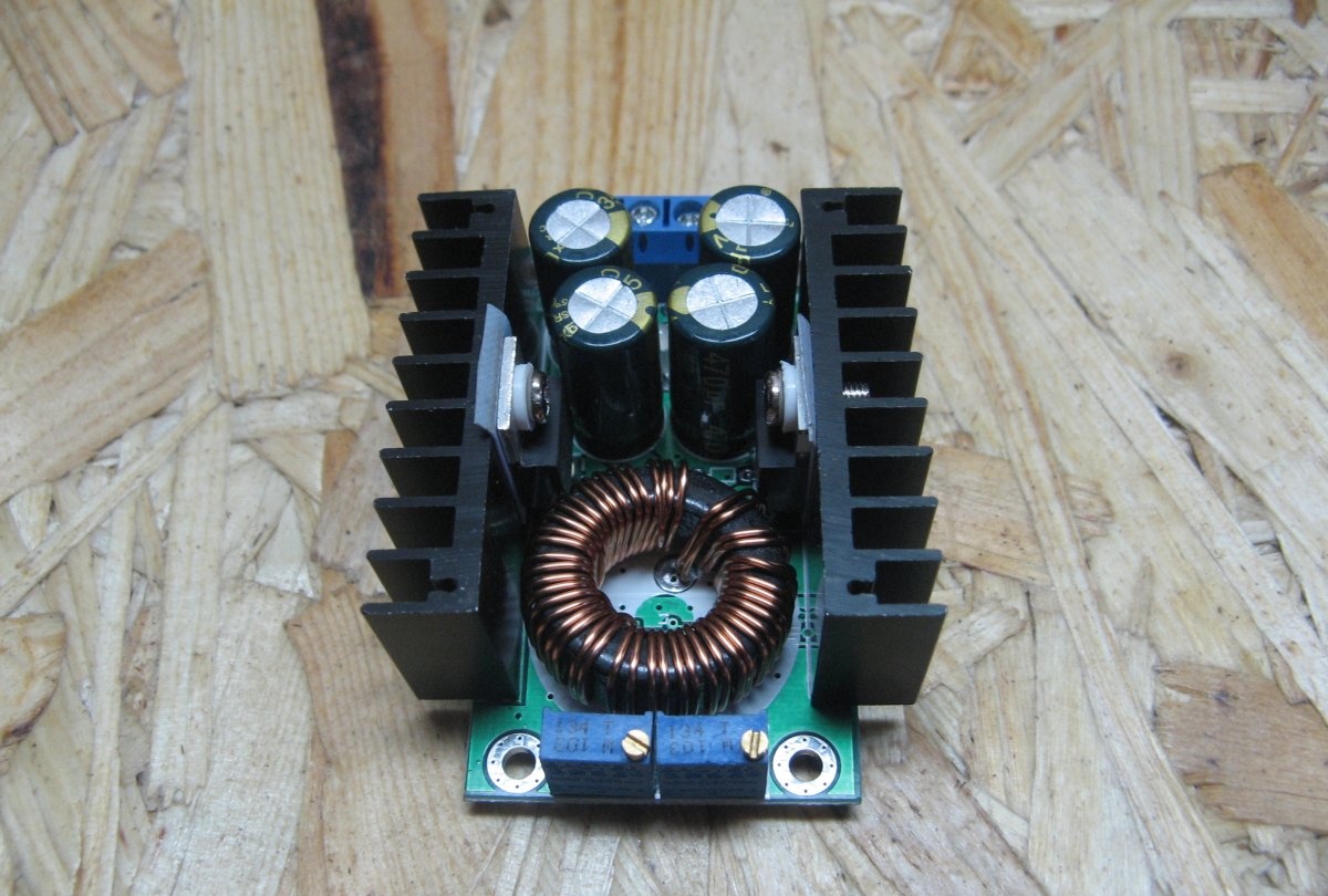
  • Output current (max) 9 Amperes, it is advisable to install a cooler.

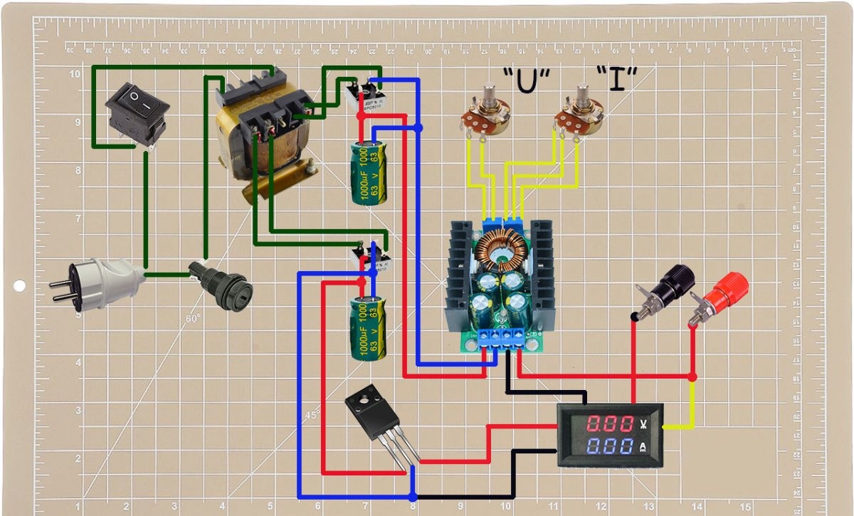
Power supply diagram


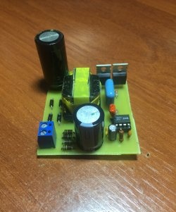
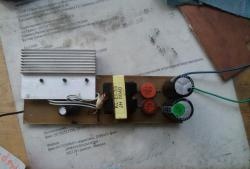
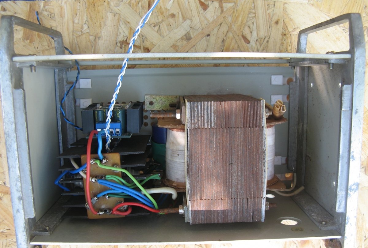
As I already said, the scheme is simple. The mains voltage is supplied to the transformer. There is a power switch and fuse. The voltage is stepped down by a transformer. The top honor of the power circuit. Alternating voltage is supplied to the diode bridge and smoothing capacitor. Next it goes to the DC-DC converter. From the converter, voltage is supplied to the output terminals. The minus of the circuit is broken by the device. For convenience, the adjustment resistors are removed from the board.
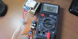
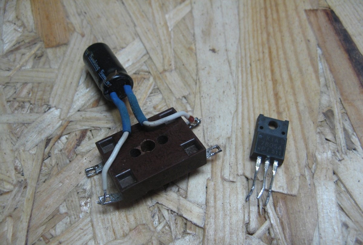
The lower one is designed to power the voltammeter. The transformer has a separate winding.As with the power winding, alternating voltage is supplied to the diode bridge and filter capacitor. Next, I installed a 5 Volt linear stabilizer.
Reliable laboratory power supply

Components


We figured out the scheme. Now let's move on to the components.
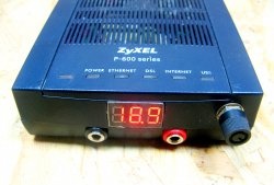
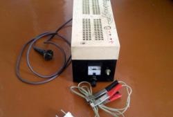
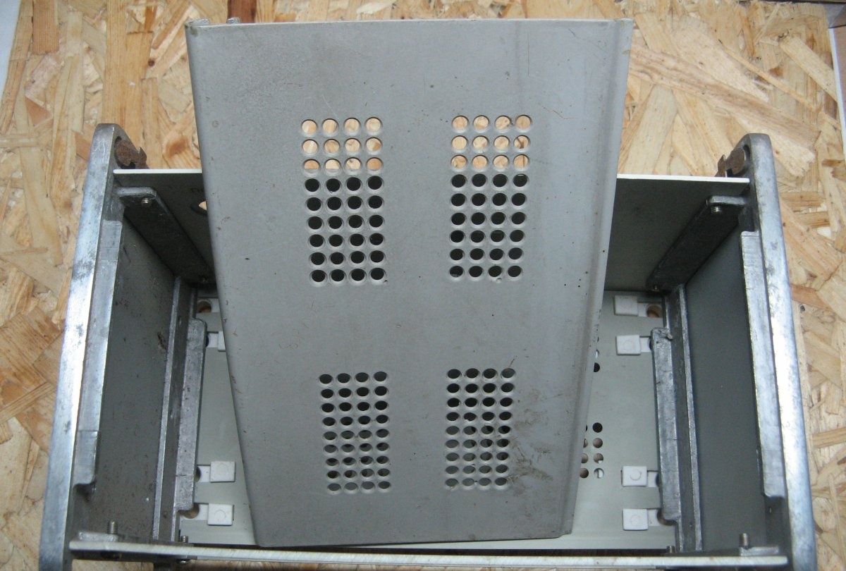
The body of the LBP will be the old body from the soldering iron regulator. The soldering iron regulator dates back to USSR times. Very kind.
Reliable laboratory power supply

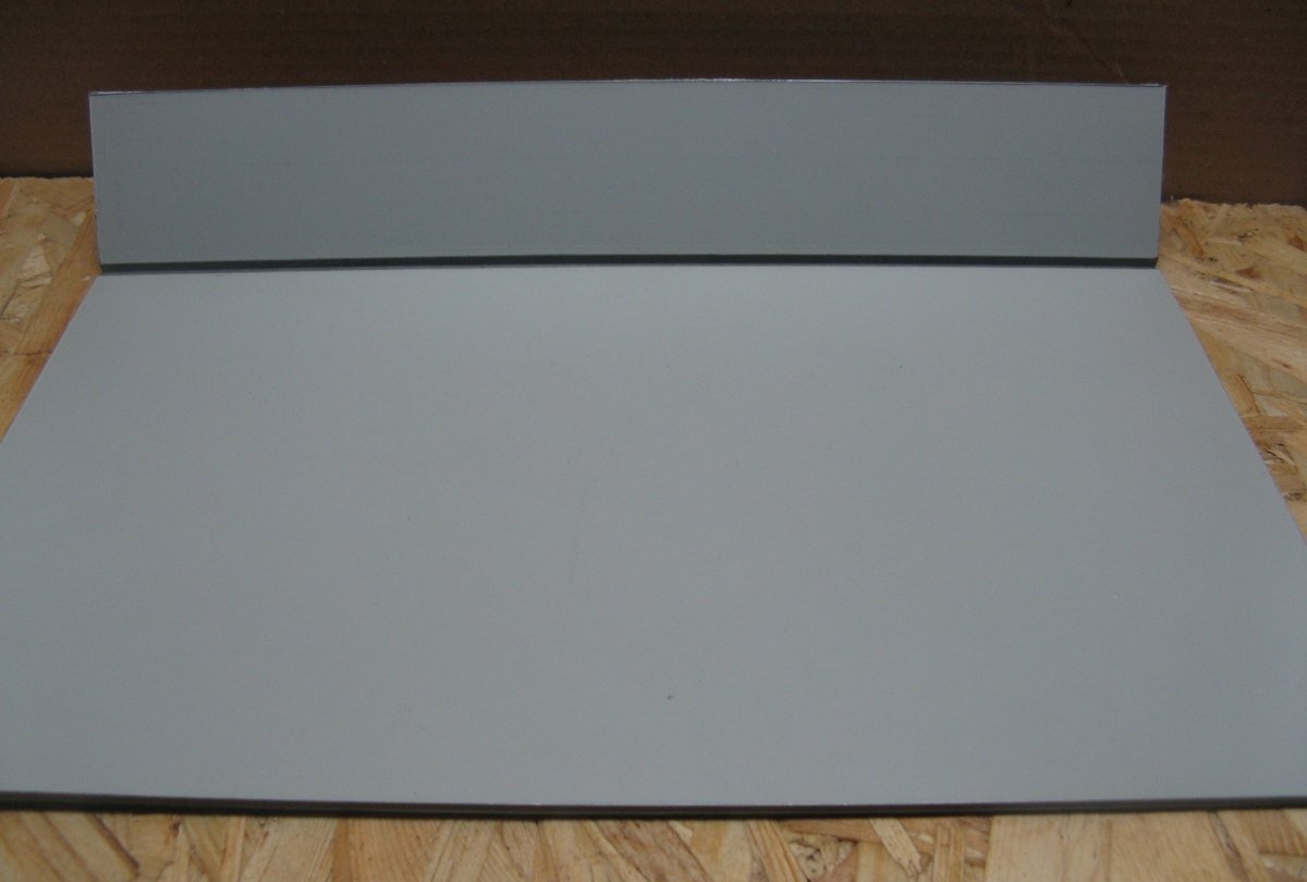
The front panel will be made of composite plastic. The plastic consists of two aluminum plates and plastic between it. On the one hand it is white, on the other it is black. The black side will be the front.
Reliable laboratory power supply

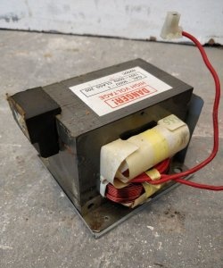
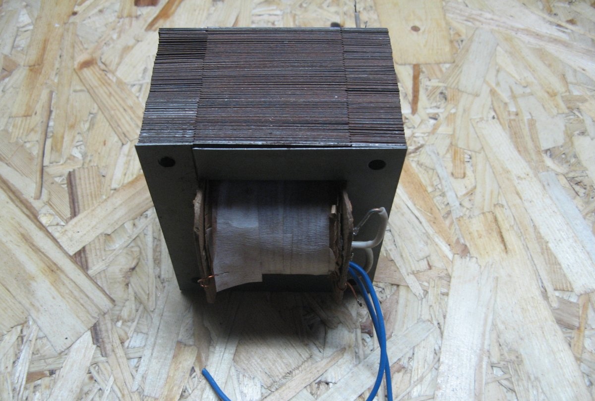
A step-down transformer from old equipment, I don’t remember which one. It had to be slightly modified. I made a tap at 22 Volts, a full winding at 27 Volts. If left, then after the diode bridge the voltage is more than 30 Volts. This is a lot for a 7805 regulator installed on a [leech=http://]DC-DC converter[/leech]. It powers the op-amp circuit. Although 40 Volts are stated, taking into account the maximum for 7805 at 30 Volts.
Reliable laboratory power supply

DC/DC Buck Converter.
Reliable laboratory power supply

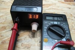
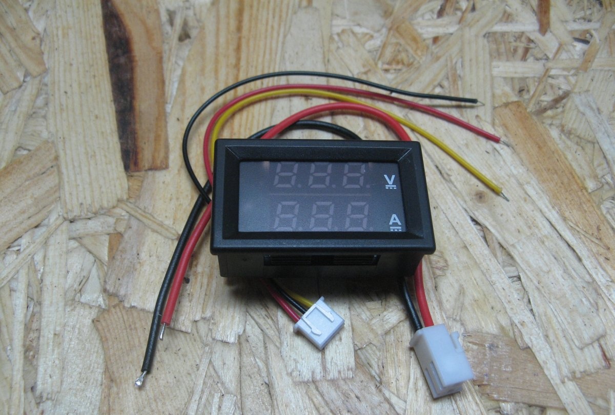
3-segment voltammeter. For a more accurate display of output parameters, you need to apply it to 4 segments. I had the one I had and used it.
Reliable laboratory power supply

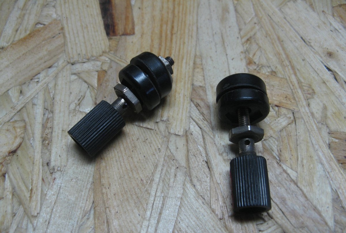
Terminals from the times of the USSR. Strong and reliable.
Reliable laboratory power supply

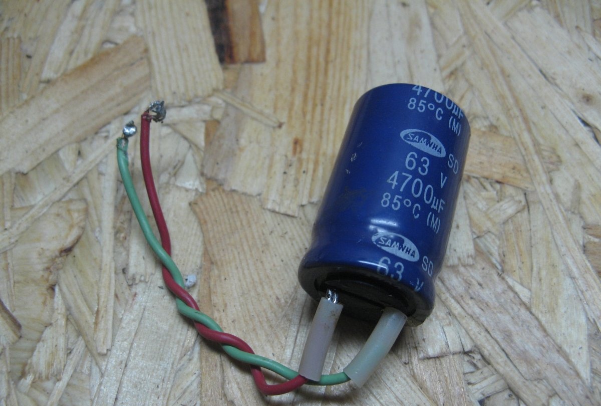
Capacitor 4700 microfarads * 63 Volts. Based on 1000 microfarads per 1 Ampere. Another 2*470 uF are installed on the module.
Reliable laboratory power supply

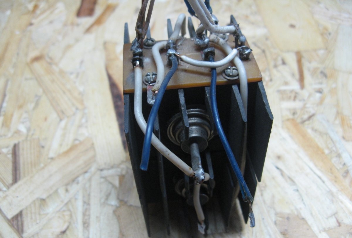
You can use a single diode bridge, but I still have it from an old project. Assembled on 4 D242 diodes.
Reliable laboratory power supply

Manufacturing


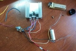
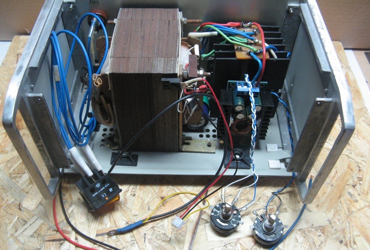
At the bottom of the case we mark and drill holes for: transformer, diode bridge, module. We solder everything according to the circuits. I removed two trimming resistors from the module. I soldered wires instead. There are 3 wires for current, two for voltage.
Reliable laboratory power supply

I will power the Voltammeter through a 5 Volt linear stabilizer.Diode bridge KTs402 and a small capacitor.
Reliable laboratory power supply

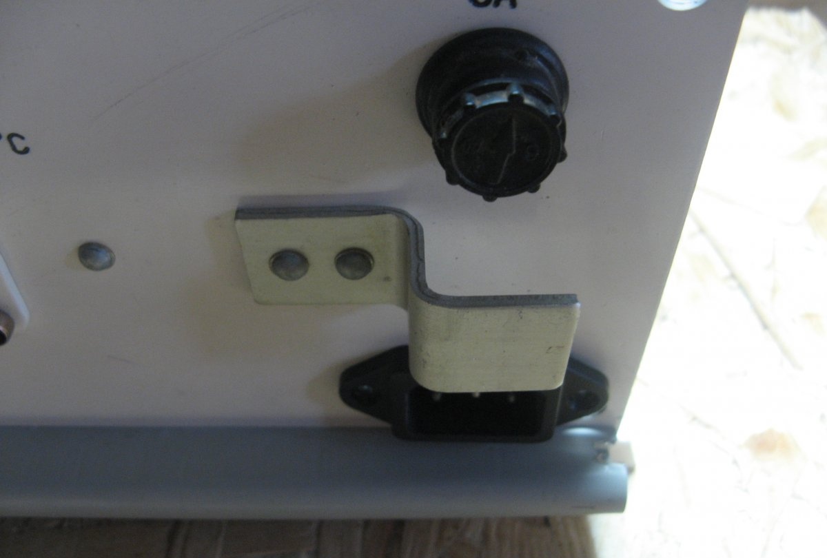
On the back panel I make markings for the power connector and fuse. I carefully cut everything out and install it.
Reliable laboratory power supply

I mark and cut out all the holes on the front panel. There will be: output terminals, mains switch, current and voltage resistors, Volt-ampere meter.
Reliable laboratory power supply

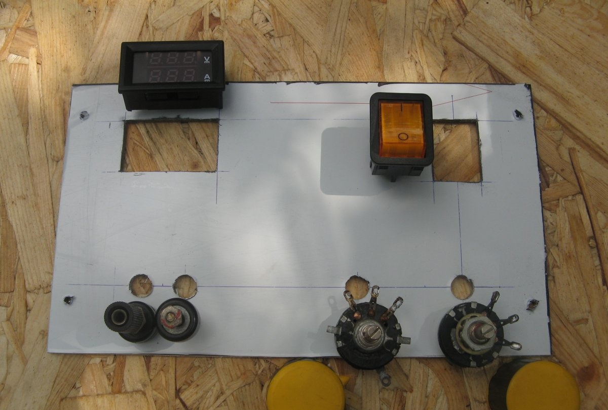
I soldered all the elements installed from the inside. The power switch switches both network wires. Initially I wanted to use another one.
Reliable laboratory power supply

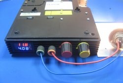
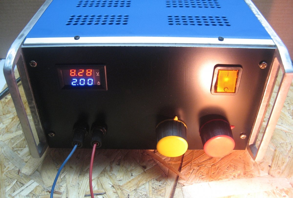
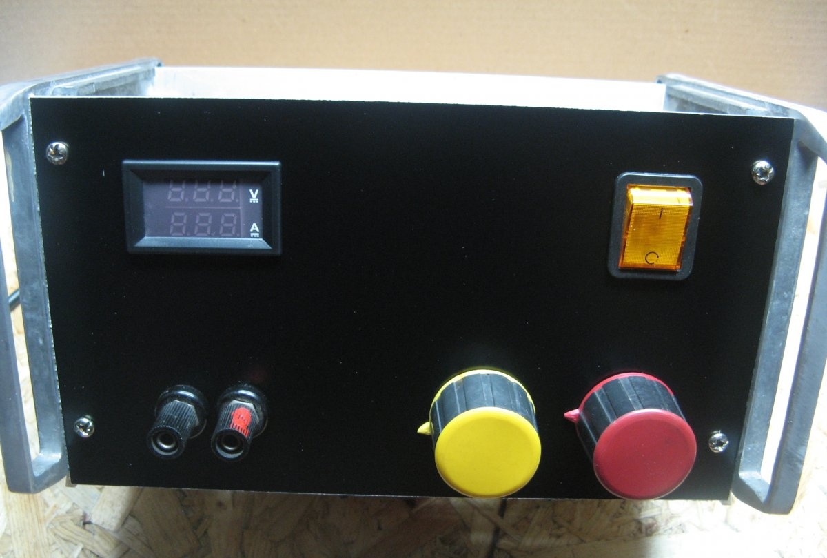
We install all the elements of the front panel. The positive terminal is marked with red paint. Resistor handles of different colors. Red is the color of the Volts display. Yellow in current. I have not yet signed where the current and voltage are. Later I will change the resistors to multi-turn ones, and perhaps change the handles too.
Reliable laboratory power supply

I painted the top cover. There was too big a gap between the front panel and the lid; it was closed with a small corner. When tested, the unit produced 9 Amperes on short, at 28 Volts, which amounted to a little more than 250 Watts.
Reliable laboratory power supply

This is how the Laboratory Power Supply turned out. They can power various types of devices and also charge batteries. Initially I wanted to use a 24 Volt pulse source, but I came across a transformer of the required dimensions. Also, I try to assemble a device from what I have. Thank you all for your attention!

Watch the video


come back
Comment
  • bowtiesmilelaughingblushsmileyrelaxed relaxedsmirk
    heart_eyeskissing_heartkissing_closed_eyesflushedrelievedsatisfiedgrin
    winkstuck_out_tongue_winking_eyestuck_out_tongue_closed_eyesgrinningkissingstuck_out_tonguesleeping
    worriedfrowninganguishedopen_mouthgrimacingconfusedhushed
    expressionlessunamusedsweat_smilesweatdisappointed_relievedwearypassive
    disappointedconfoundedfearfulcold_sweatperseverecrysob
    joyastonishedscreamtired_faceangryragetriumph
    sleepyyummasksunglassesdizzy_faceimpsmiling_imp
    neutral_faceno_mouthinnocent
5+two=
Comments (11)
  1. ElektoLekhych
    #1 ElektoLekhych Guests 4 September 2018 10:51
    1
    Has anyone tried it? Does it work mentally or with blunts?
    1. Guest Victor
      #2 Guest Victor Guests 5 September 2018 10:13
      4
      I drove this module. He fed both trance and impulse. It pulls great.
    2. Guest Andrey
      #3 Guest Andrey Guests June 1, 2020 05:00
      3
      I tried to use a Chinese DC-DC step-down unit to regulate the voltage and current of my power supply with the following result: the first "Chinese" worked for several days and failed. I bought two more. The second and third worked for only a few minutes before failing. The first loaded the load at a current of 6A, the second and third - in the region of 3A.
  2. Sergey K
    #4 Sergey K Visitors September 5, 2018 00:15
    2
    Why do you ask to use a regular transformer and install a pulse device behind it? There will be interference no matter what, and the price of transformers is off the charts. It is more logical to use an electronic transformer.
    I did this, 24V 3A output, protection, indication. I still can’t get around to describing a super budget power supply.
    But it is not laboratory, which is usually understood as a power supply without impulse noise.
  3. Sergey K
    #5 Sergey K Visitors September 5, 2018 00:18
    1
    To have a normal laboratory test, instead of a pulse converter, it is better to install a regular linear stabilizer with a large radiator. There is space in the building. Such microcircuits can be desoldered on old motherboards ;)
  4. Vladimir.
    #6 Vladimir. Guests September 5, 2018 09:59
    2
    Why a transformer? And it can lie idle. If it already exists, then why not.
    1. popvovka
      #7 popvovka Guests 5 September 2018 20:56
      1
      Your comment is spot on!)
    2. Sergey K
      #8 Sergey K Visitors 7 September 2018 15:16
      0
      Maybe... With this approach, it turns out that most of the schemes from the Radio magazine were invented by enthusiasts who had something lying around, and when they try to repeat it, it turns out that the parts can only be obtained from insanely expensive equipment. Well, or wait until this equipment comes across in a landfill...
      1. Guest Victor
        #9 Guest Victor Guests 7 September 2018 16:43
        1
        The same can be said about cars. There are parts worth a lot of money that can be ordered. Without them, the car will not drive or act up. So, don't repair it, but wait for disassembly?
  5. Guest Vladimir
    #10 Guest Vladimir Guests 5 September 2018 22:33
    1
    I made several pieces on this basis. They work. But I installed multi-turn resistors. It’s more convenient
  6. Guest Alexander
    #11 Guest Alexander Guests January 18, 2019 00:34
    0
    What are the values ​​of variable resistors?

How to reduce HDD noise to a minimum

Beaded keychain “Crocodile” | Do it yourself

Hair decoration: “Balls and beads” | Do it yourself

Chicken marinated in beer and mustard | Do it yourself

«Do it yourself - with your own hands» - a site of interesting homemade products made from scrap materials and items at home. Step-by-step master classes with photos and descriptions, technologies, life hacks - everything a real master or just a craftsman needs for needlework. Crafts of any complexity, a large selection of directions and ideas for creativity.

We recommend reading

Washing machine error codes